Section 5
MODIFICATION KITS
5.0 General - A number of optional features in the form
of Modification Kits are offered with the FlexPak Plus con-
troller . Each of these Kits extends the control of the unit and
tailors its operation to specific application needs .
This Section describes the procedures that must be fol-
lowed to install the Kits. Refer to Table 5.A for an informa-
tional listing.
DANGER
INSTALLATION OF MODIFICATION KITS IS TO BE
DONE ONLY AFTER A-CLINE VOLTAGE IS DIS-
CONNECTED AND LOCKED OUT AT THE MAIN
DISCONNECT SWITCH. DO NOT INSTALL KITS
WHEN POWER IS APPLIED TO THE FLEXPAK
PLUS CONTROLLER. SERIOUS PERSONAL INJURY
AND EQUIPMENT DAMAGE COULD RESULT.
CAUTION:
Installation of the Modification Kits should
be performed only by qualified electrical maintenance
personnel familiar with the design and operation of
this equipment. Damage could result thru unfamil-
iarity .
Many of the Modification Kits are designed to make electri-
cal connection with the Regulator Module hy means of
pin-type connectors. These slide up
tr· r ,h matching
holes in the Modules that form part ti Kit . (Refer to
Figur e 5.1 .)
Figure 5 .1 - Pin Alignment
A common installation probl em is caused by bent, broken
or incorrectly placed pins . Since imprope r operation
result s, care must be taken . Exact alignment is critical.
Visually check that only
one pin extends to the top of each
slot on ce the connection is made .
Many of the Modifi cation Kits require the removal of one or
more jumpers from the Regulator Module. In such cases,
carefully clip the leads on
both sides of each jumper and
discard it . Use a sharp pair of dykes (diagonal cutters) to
assure a quick, clean cut. Do not twist the tool , since dam-
age may result.
In cases where th e Kit is secured by a mounting screw, be
sure to tight en it firmly but
do not overtighten . Excess ive
force can strip the threads.
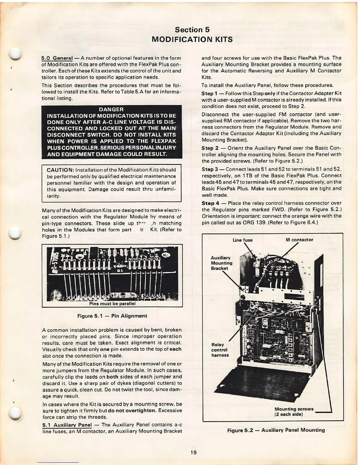
5.1 Auxiliary Panel - The Auxiliary Panel contains a-c
line fuses. an M contactor, an Au xiliary Mounting Bracket
19
and four screws for use with the Basic FlexPak Plus . The
Auxiliary Mounting Bracket provides a mounting surface
for the Automatic Reversing and Auxiliary M Contactor
Kits.
To install the Au xi liary Panel, follow these procedures .
Step 1 - Follow this Step only if the Contactor Adapter Kit
with a user-supplied M contactor is already installed. If this
condition does not exist , proceed to Step 2.
Disconnect the user- supp lied FM contactor (and user-
supplied RM contactor if applicable}. Remove the two har-
ness connectors from the Regulator Module . Remove and
discard the Contactor Adapter Kit (including the Auxiliary
Mounting Bracket} .
Step 2 - Orient the Auxiliary Panel over the Basic Con-
troller aligning the mounting holes. Secure the Panel with
the provided screws . (Refer to Figure 5.2 .)
Step 3 - Connect leads 51 and 52 to termina ls 51 and 52 .
respectively , on 1 TB of the Basic FlexPak Plus. Connect
leads45 and 47 toterminals45 and 47 , respectively , on the
Basic FlexPak Plus. Make sure connections are tight and
well made .
Step 4 - Place the relay control harness connector over
the Regulator pins marked FWD . (Refer to Figure 5.2.)
Orientat ion is important : connect the orange wire with the
pin called out as ORG 139. (Refer to Figu re
6.4.)
Line fuse
M contactor
Mounting screws
(2 each side)
Figure 5.2 - Auxiliary Panel Mounting