The Operator Control Station AUTO / MANUAL selector
switch is used to obtain local control or master reference
control of the individual drive. When the selector switch is
placed in the AUTO mode, the individual drive SPEED
Potentiometer automatically is converted into a draw pot
adjustment for precise tFim control between drives. The
only adjustment requirement is a zero set adjustment on
the Reference Receiver Module. Should the speed refer-
ence wires become disconnected, the FlexPak Plus will go
to zero speed.
FlexPak Plus controllers controlled by Master Isolated Ref-
erence are ideally suited for non-reversing multiple con-
veyor drives, proportional pumps, feeder drives, web lines
or other similar operations which require multiple drives to
follow a common reference signal .
To install the Kit, follow these procedures.
Step 1 - Refer to Figure 6.4 and note the heavy border
area atthe extreme left-hand side of the Regulator Module.
This is the area where the Switch Receiver Module is to be
mounted. First, remove the Remote Operator Adapter
Module. Then, place the Switch Receiver Module in the
proper orientation so the two connectors are aligned over
the two sets of pins (marked GRN 28 and RED 32). Care-
fully, slowly and gently press the connectors down on the
pins until they bottom . Then, connect the black pig-tail
jumper of the Switch Receiver Module to pin 40 on the
Regulator Module. (Pin 40 is the left-hand pin of the group
marked AUTO REV.).
Step 2 - Fold the PC board over the top of the two connec-
tors so the mounting spacers fit into the mounting holes .
Step 3 - Connect the external start-stop wires (wires 189
and 288) from the external Master Isolated Reference
Transmitter to the terminal block on the Switch Receiver
Module in the controller cabinet.
Step 4 - Mount the Remote Operator Adapter Module on
top of the Switch Receiver Module and secure the two PC
boards with the two long screws provided.
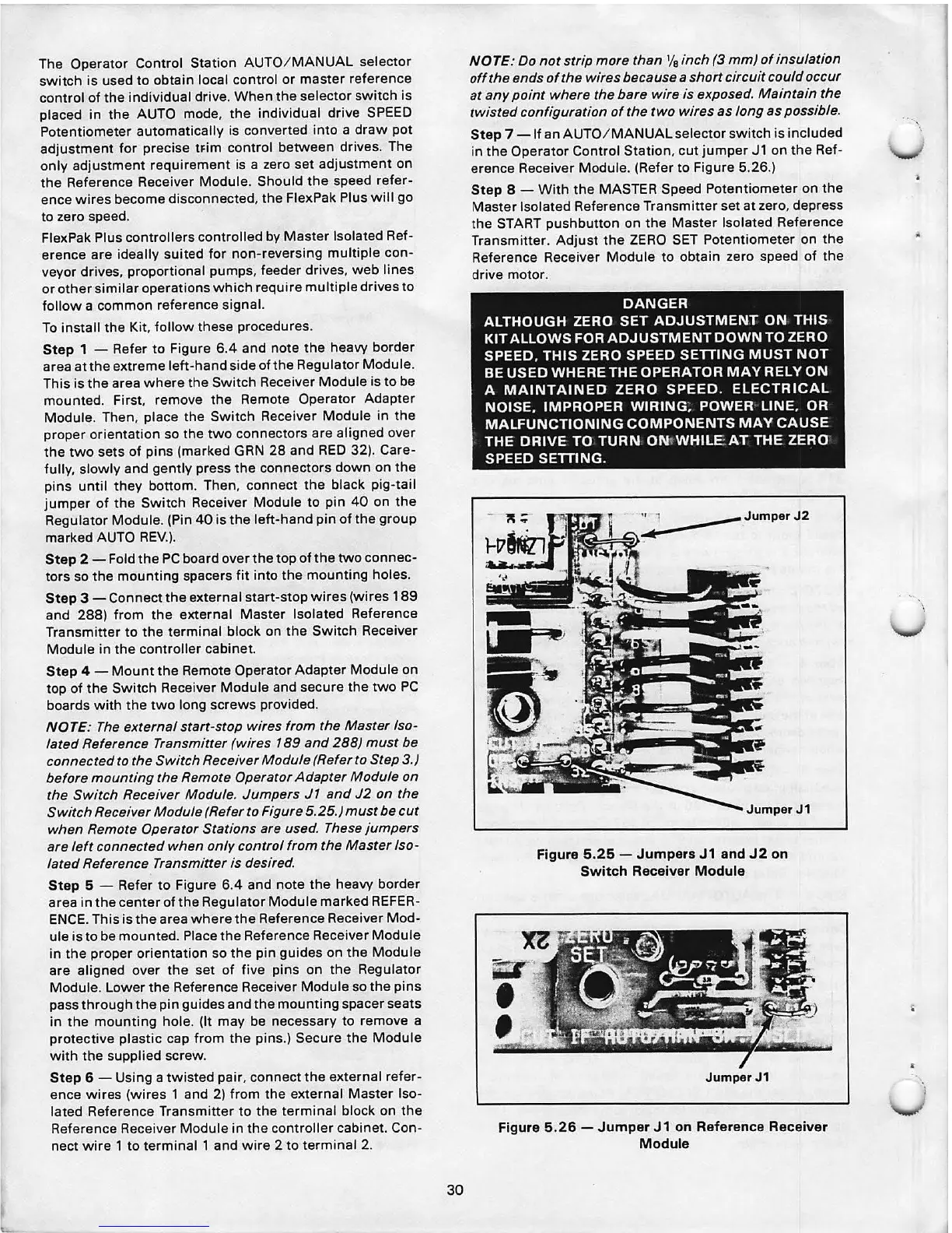
NOTE : The external start -stop wires from the Master Iso-
lated Reference Transmitter (wires 189 and 288) must be
connected to the Switch Receiver Module (Refer to Step 3.)
before mounting the Remote Operator Adapter Module on
the Switch Receiver Module. Jumpers J1 and J2 on the
Switch Receiver Module (Refer to Figure 5.25.) must be .cut
when Remote Operator Stations are used. These jumpers
are left connected when only control from the Master Iso-
lated Reference Transmitter is desired.
Step 5 - Refer to Figure 6.4 and note the heavy border
area in the center of the Regulator Module marked REFER-
ENCE. This is the area where the Reference Receiver Mod-
ule is to be mounted. Place the Reference Receiver Module
in the proper orientation so the pin guides on the Module
are aligned over the set of five pins on the Regulator
Module. Lower the Reference Receiver Module so the pins
pass through the pin guides and the mounting spacer seats
in the mounting hole. (It may be necessary to remove a
protective plastic cap from the pins.) Secure the Module
with the supplied screw.
Step 6 - Using a twisted pair, connect the external refer-
ence wires (wires 1 and 2) from the external Master Iso-
lated Reference Transmitter to the terminal block on the
Reference Receiver Module in the controller cabinet. Con-
nect wire 1 to terminal 1 and wire 2 to terminal 2.
30
NOTE: Do not strip more than
1
/
8
inch (3 mm) of insulation
off the ends of the wires because a short circuit could occur
at any point where the bare wire is exposed. Maintain the
twisted configuration of the two wires as long as possible.
Step 7 - If an AUTO/ MANUAL selector switch is included
in the Operator Control Station, cut jumper
Jl on the Ref-
erence Receiver Module. (Refer to Figure 5.26.)
Step 8 - With the MASTER Speed Potentiometer on the
Master Isolated Reference Transmitter set at zero, depress
the START pushbutton on the Master Isolated Reference
Transmitter . Adjust the ZERO SET Potentiometer on the
Reference Receiver Module to obtain zero speed of the
drive motor.
DANGER
ALTHOUGH ZERO SET ADJUSTMENT ON THIS
KIT ALLOWS FOR ADJUSTMENT DOWN TO ZERO
SPEED. THIS ZERO SPEED SETTING MUST NOT
BE USED WHERE THE OPERATOR MAY RELY ON
A MAINTAINED ZERO SPEED. ELECTRICAL
NOISE. IMPROPER WIRING; POWER LINE, OR
MALFUNCTIONING COMPONENTS MAY CAUSE
THE DRIVE TO TURN
ONtWHILEAT THE ZERO
SPEED SETTING.
JumperJ1
Figure 5.25 - Jumpers J1 and J2 on
Switch Receiver Module
Jumper J1
Figure 5.26 - Jumper J1 on Reference Receiver
Module
\
\