Table 6.A
• Figure 6.4 which is a copy of the screen used to mark
the Regulator Module. It is useful in identifying loca-
tions on the board. Note that areas where optional
Modification Kits fit are marked with heavy lines.
COLOR CODING SYSTEM
• Figure 6.5 which is a schematic for the controller.
• Figure 6.6 which is a schematic for the Modification
Kits.
• Figure 6.7 which may be used to locate major assem-
blies in the controller. It also lists various technical
data although all of this information is included in
other parts of the manual.
COMPONENTS
Relay Wire Harness
(forward)
Relay Wire Harness
(Reverse)
Thermostat Harness
Gate Harness
Auto Reverse
Auxiliary M
Control transformer secondary winding.
481
FM
., 1---- .......
FM
-i .... f---065
14----- approx. 24 voe
r-~OP- - START i :~;
NO.
139
36
65
39
38
66
67
38
139
36
32
132
47
45
40
39
I _I_, 38 J9 1-1
U----1-LWII-...... •---
1
-----------Q- ...... ( )-+- - -
132 32 L _ _ _ J 39 FM
RUN
L, 1K
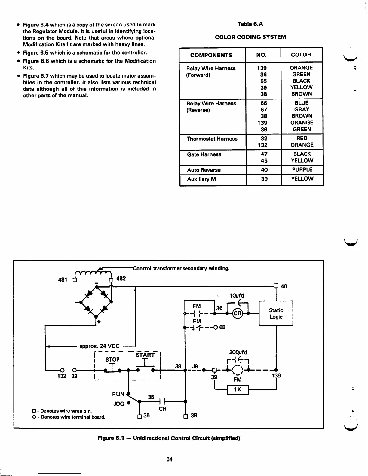
D - Denotes wire wrap pin.
0 - Denotes wire terminal board.
38
Figure 6. 1 - Unidirectional Control Circuit (simplified)
34
Static
Logic
139
I
COLOR
V
ORANGE
GREEN
BLACK
YELLOW
BROWN
BLUE
GRAY
BROWN
ORANGE
GREEN
RED
ORANGE
BLACK
YELLOW
PURPLE
YELLOW
V
V