6. SERVICE REM - GRAINVAC VR12
6.2. F
LIGHTING REMOVAL/REPLACEMENT
74 9000-00-0042 R3
6.2. Flighting Removal/Replacement
1. To remove and replace the lower and middle flighting, follow these steps:
a. Remove the two bolts on the bearing support.
b. Remove the flighting.
c. To replace, slide the flighting back into the auger tube. Verify this by opening the
side inspection door and verifying the drive dogs are fully engaged at the gearbox.
Rotate the flighting until the gearbox drive dogs engage. Note: Middle flighting
does not require drive dog alignment.
d. Install the two bolts onto the bearing support.
2. To remove and replace the upper flighting section, follow these steps:
a. Remove the snap ring on the end of the flighting.
b. Loosen the lock collar on the bearing.
c. Remove the flighting.
d. To replace, slide the flighting all the way into the bearing and lock collar, install the
snap ring, and pull the flighting down.
e. Raise the auger to working position (fully raised).
Stay away from auger tubes when opening/closing (due to pinch
points). Keep others away. Failure to do so may result in serious
injury or death.
f. Engage the GrainVac to activate the augers. Run for 1 minute at low engine idle.
g. Lock out the power unit and inspect the top bearing. If the top bearing is not
sealing to the end of the dumper, note the distance between them (example: 1/8”
(3 mm)).
h. Tighten the lock collar on the bearing.
i. Lower the auger so that it fully rests on the auger transport rest. Lock out the power
unit.
j. On the upper auger, loosen the lock collar on the dumper bearing and slide the
upper flighting up the distance that you noted with the augers in working position
(fully raised).
k. Tighten the lock collar on the bearing.
l. Repeat step e. through step k. until the dumper bearing is seated fully against the
end of the dumper.
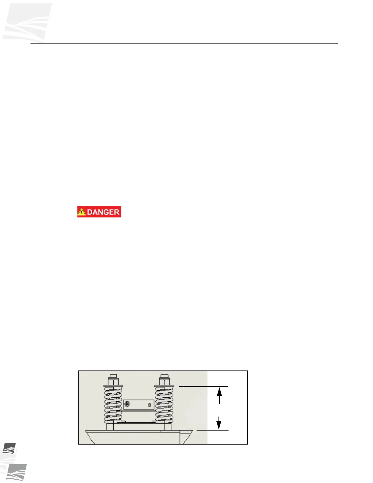
m. Ensure end dump bearing springs are adjusted to the dimension in Figure 6.1.
Figure 6.1 End Dump Bearing Spring Dimension
3” (76 mm)
END DUMP AUGER TUBE