6. SERVICE REM - GRAINVAC VR12
6.4. S
PLIT TAPER BUSHING – REMOVAL & INSTALLATION
80 9000-00-0042 R3
6.4. Split Taper Bushing – Removal & Installation
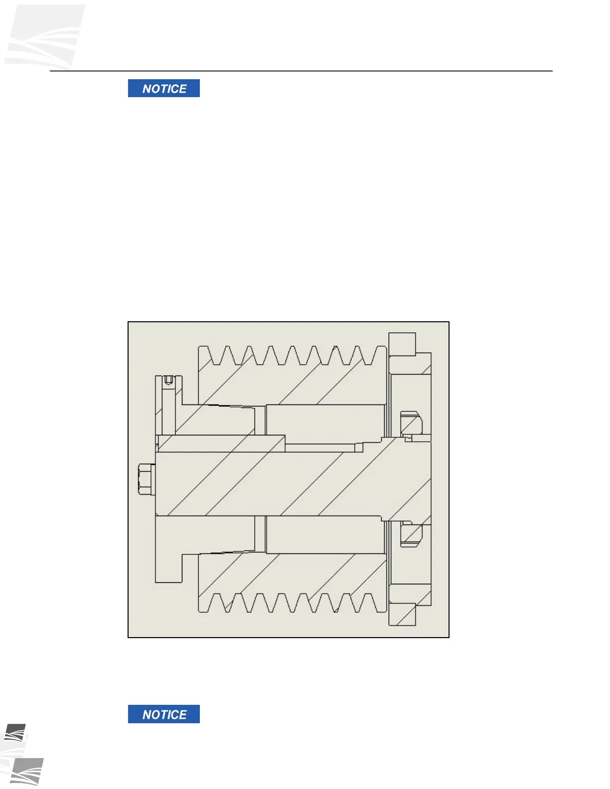
Never allow the sheave to be drawn in contact with the flange of the
bushing. This gap should measure from 1/8” to 1/4” (3.2 mm to 6.4
mm). If extreme screw tightening forces are applied, excess
pressures will be created in the hub of the mounted sheave which
may cause it to crack.
To remove bushing flange away from the machine:
• Remove the cap screws and thread into the tapped holes in the bushing flange.
Tighten progressively until the bushing is free from the sheave taper.
• Remove the assembly from the shaft.
To install bushing flange away from the machine:
• Align the drilled holes in the bushing flange with the tapped holes in the sheave hub.
• Insert the cap screws through the drilled holes in the bushing flange and thread
loosely into the tapped holes in the sheave hub.
• Position the assembly on the shaft and tighten the cap screws progressively and uni-
formly.
Figure 6.6 Bushing Flange Away from Machine
If the bushing is completely removed from the sheave, use the following cleaning
procedure:
• Oil or grease may be removed with a suitable cleaner or solvent.
The removal of all traces of oil or grease from the mating surfaces of
the bushing or sheave is critical to prevent sheave failure during the
assembly process.