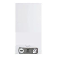
Remeha Selecta
24
4.6.6 Heating Water flow
The modulating controller of the appliance limits the maximum temperature difference
between flow and return. As a result, the appliance should not be effected by low
water flow. Therefore a system by-pass is not neccesary, however building regulations
should be complied with.
4.6.7 Water connections
The water connections are located on the bottom of the boiler (see Fig. 03 and Fig.
04). The CH connections are 22 mm Ø o/d. The DHW connection and cold water inlet
are both 15 mm Ø o/d. When using the mounting frame connect to the isolation valves
supplied. A 10 ltr. flow restrictor is supplied with the boiler and should be installed into
a compression fitting directly onto the cold water inlet connection to the boiler.
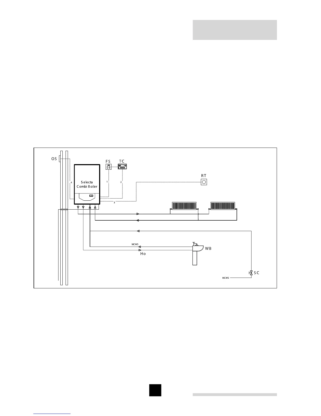
Fig. 14 Hydraulical example Selecta combi boiler (use in conjunction with electrical
drawing Fig. 17)
pdf
Cable legend
1 = 3 amp fused supply (not supplied)
2 = external volt free switching time
clock (not supplied)
3 = room thermostat (not supplied)
4 = outside sensor (not supplied)
Legend
OS = outside sensor (optional)
FS = 3 amp permanent fused supply (not supplied)
TC = external time clock with volt free switching
(not supplied)
RT = room thermostat (not supplied)
WB = wash hand basin
SC = stop cock
Ho = hot water outlet