31
7 CONTROLS
7.1 Control box
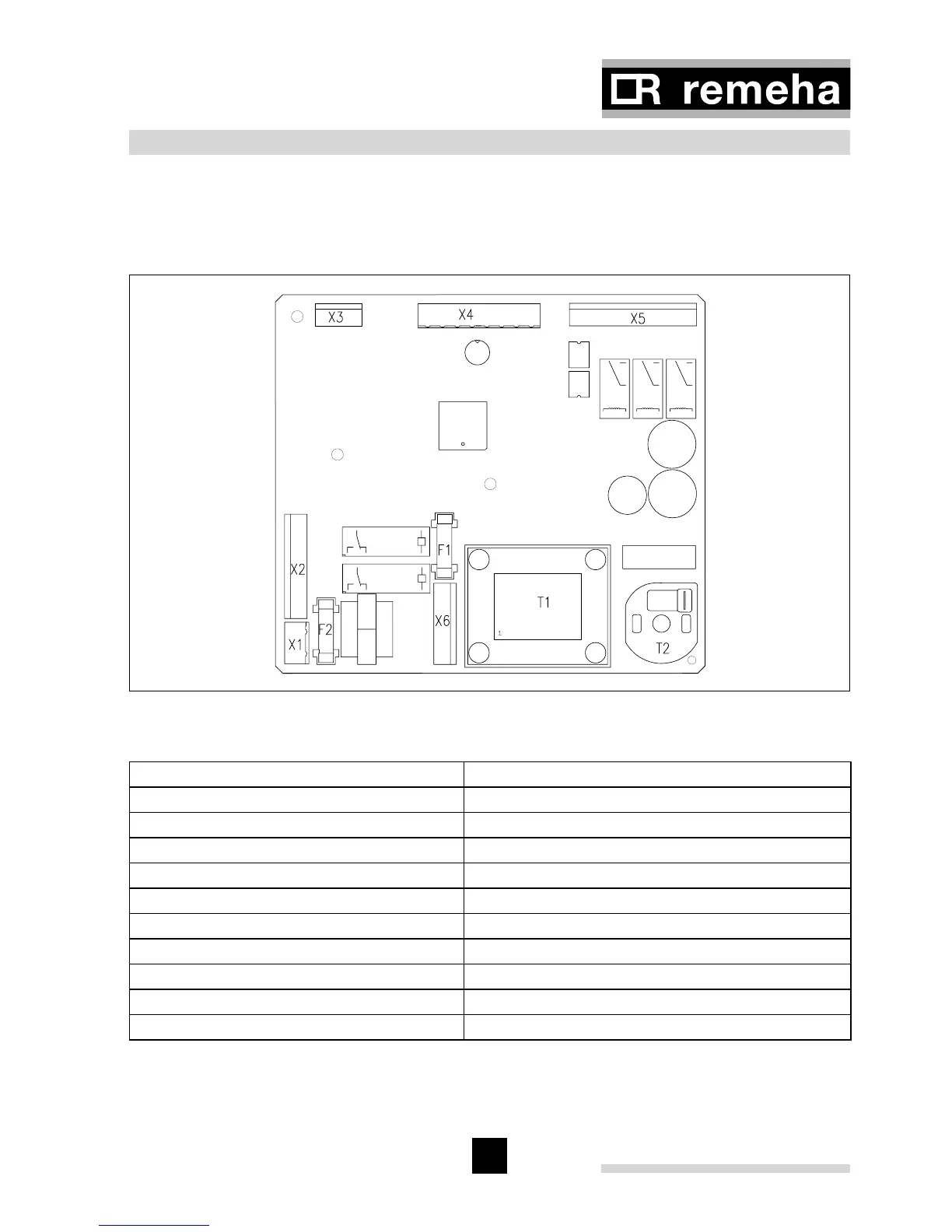
Fig. 19 shows the layout of the control box. This sketch shows where the connectors
and fuses are positioned. Table 05 sums up the main characteristics of the control box.
Fig. 19 Control box
04.W5H.79.00008
Make GasModul Type MCBA 1459D
Mains voltage 230 VAC/50Hz
Pre-purge time 3 s
Post-purge time 3 minutes
Ignition time 2.4 s
Gas valve opening time 2.7 s
Anti-cycling time 150 s
Pump overrun C.H. position Adjustable (see Par. 4.6.5)
Fuse value F1 (230V) 2 amp fast blow 20 mm glass fuse*
Fuse value F2 (24V) 4 amp slow blow 20 mm glass fuse*
DC-fan 24 VDC
Table 05 Characteristics control unit
* According to BS EN 60 127-2:1991