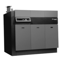
Remeha Selecta
32
7.2 Boiler control
7.2.1 Introduction
The Remeha Selecta can be controlled in three ways:
1. Simple time clock and on / off room thermostat, whereby the boiler output varies
between the minimum and the maximum to maintain the flow temperature set point
on the boiler. If an outdoor sensor is also connected the flow temperature is deter-
mined by the outside temperature and the compensation graph detailed in Fig. 20.
2. Modulating OpenTherm
®
room controller, whereby the boiler output varies between
the minimum and the maximum to maintain the temperature determined by the
modulating controller.
3. Outside sensor and simple time clock, whereby the boiler output varies between
the minimum and the maximum to maintain the flow in accordance with the com-
pensation graph shown in Fig. 20.
7.2.2 Simple time clock and on/off room thermostat (control based on time and
room temperature)
The Remeha Selecta is suitable for connecting a 2-wire 24V (or volt free) on/off room
thermostat, which should be connected to terminals 2 and 3 on the terminal connector X4.
7.2.3 Modulating OpenTherm
®
room controller (control based on time and
room temperature)
Using a modulating room controller takes full advantage of the modulating
characteristics of the boiler. The modulating room controller communicates with the
boiler and based on the room temperature, the modulating room controller constantly
modifies the boiler flow temperature, based on system demand. This ensures that
the boiler’s output closely follows the property demand and prevents on/off cycling
resulting in higher efficiencies.
The Remeha Selecta is prepared for communication via the “OpenTherm
®
” protocol.
An suitable “OpenTherm
®
” modulating room controller is available from Broag.
The controller should be mounted in a suitable reference room. Connection is made
with a twin cable (0.75 mm) to terminals 5 and 6 of the terminal connector, see Fig. 16.
Attention: For DHW production the boiler and controller must be set to the same
temperature demand otherwise the controller setting will take priority.
7.2.4 Outside-temperature sensor (control based on outside temperature and
settings as in Fig. 20)
When an outside-temperature sensor is connected to terminals 7 and 8 of connector
X4 (see Fig. 16), the weather dependant heating control will be active if the following
requirements have been met: