25
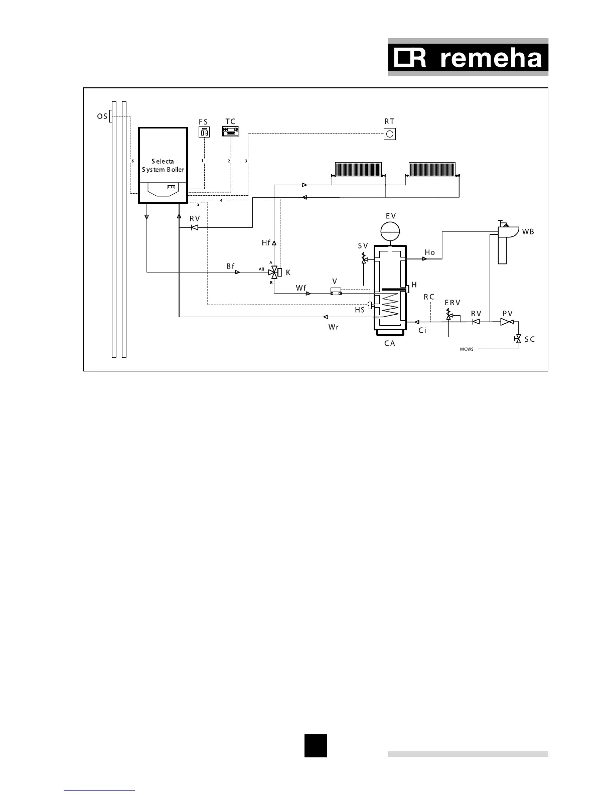
Fig. 15 Hydraulical example Selecta system boiler (use in conjunction with electrical
drawing Fig. 18)
pdf
4.6.8 Filling the system/ make up water
For initial filling and topping up, the system must be connected to the mains cold water
using a standard mains fill kit (which complies with local water byelaws) and pressu-
rised to 1 bar.
Cable legend
1 = 3 amp fused supply (not supplied)
2 = external volt free switching time clock
(not supplied)
3 = room thermostat (not supplied)
4 = diverting valve cable (
supplied with optional kit No. 1)
5 = HWS sensor cable
(supplied with optional kit No. 1)
6 = outside sensor (optional)
Legend
OS = outside sensor (optional)
FS = 3 amp permanent fused supply
(not supplied)
TC = external time clock with volt free
switching (not supplied)
RT = room thermostat (not supplied)
WB = wash hand basin
SC = stop cock
Ho = hot water outlet
Ci = cold water inlet
Hf = heating circuit flow
Bf = boiler flow
Wf = hot water primary flow
Wr = hot water primary return
K = kit No. 1 - 3 port diverting valve (optional)
V = 2 port valve
HS = sensor to be immesed inside
thermostat pocket
SV = temperature and pressure safety valve
EV = expansion vessel
H = immersion heater
RC = optional secondery return connection
ERV = expansion relief valve
PV = pressure reducing valve
RV = non return valve
CA = stainless steel calorifier