51
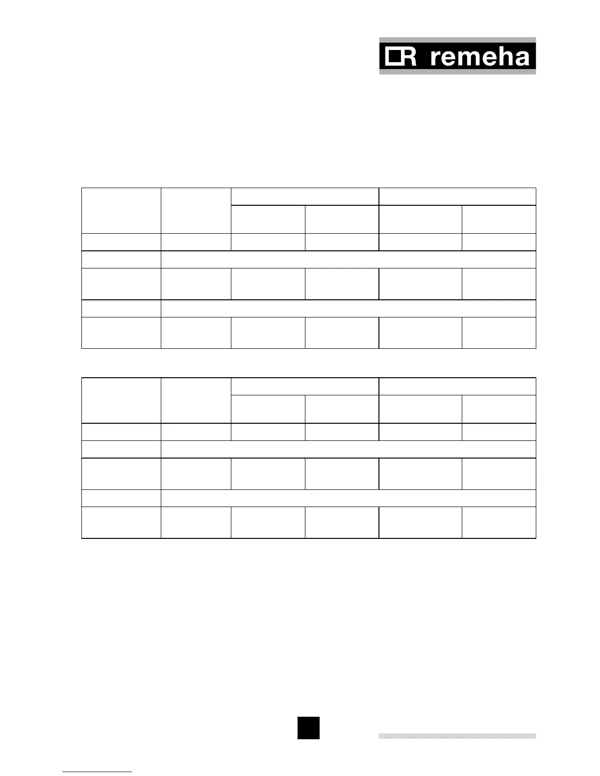
Note: When checking combustion the C0
2
levels should be in accordance with the
Table 12 (+/- 0.3%). If the levels are outside these tolerances clean heat exchanger
in accordance with the instructions in Par 11.3. If, after cleaning, the combustion fig-
ures are still outside these tolerances, then adjustments must be made to achieve the
levels in accordance with the tolerance in Table 13 (+/- 0.1%)
Fan
Speed
approx.
Natural gas Propane
CO
2
O
2
CO
2
O
2
rpm % % % %
Front panel not mounted
Part load
Full load
2300
5450
9.3 (+/- 0.3)
9.3 (+/- 0.3)
4.3 (+/- 0.4)
4.3 (+/- 0.4)
10.5 (+/- 0.3)
10.5 (+/- 0.3)
5.1 (+/- 0.4)
5.1 (+/- 0.4)
Front panel mounted
Part load
Full load
2300
5450
9.5 (+/- 0.3)
9.5 (+/- 0.3)
3.9 (+/- 0.4)
3.9 (+/- 0.4)
10.7(+/- 0.3)
10.7(+/- 0.3)
4.8 (+/- 0.4)
4.8 (+/- 0.4)
Table 12 CO
2
and O
2
percentage (checking values)
Fan
Speed
approx.
Natural gas Propane
CO
2
O
2
CO
2
O
2
rpm % % % %
Front panel not mounted
Part load
Full load
2300
5450
9.3 (+/- 0.1)
9.3 (+/- 0.1)
4.3 (+/- 0.2)
4.3 (+/- 0.2)
10.5 (+/- 0.1)
10.5 (+/- 0.1)
5.1 (+/- 0.1)
5.1 (+/- 0.1)
Front panel mounted
Part load
Full load
2300
5450
9.5 (+/- 0.1)
9.5 (+/- 0.1)
3.9 (+/- 0.2)
3.9 (+/- 0.2)
10.7(+/- 0.1)
10.7(+/- 0.1)
4.8 (+/- 0.1)
4.8 (+/- 0.1)
Table 13 CO
2
and O
2
percentage (setting values)
Attention: Make sure the opening around the probe is properly sealed off when
measuring!
The CO/CO
2
ratio should not exceed 0.02% at any time.
Maximum CO levels permitted = 100 ppm.
11.2.2 CO
2
/O
2
adjustment
The CO
2
and O
2
levels can be adjusted by following the procedure below. Any adjust-
ment required can be done via the setting screws on the gas block, see Fig. 23.