Remeha Selecta
52
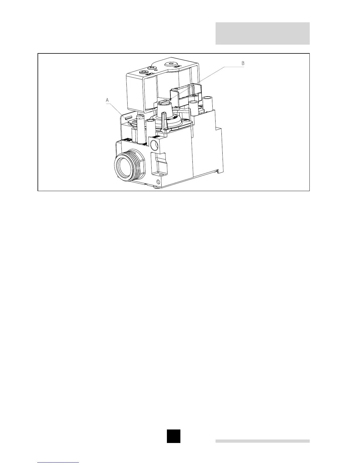
Fig. 23 Setting screws
00.W5H.79.00005
Procedure:
- Remove the boiler front panel (see Par. 8.1).
- Set the boiler to 'Forced High' mode, (see Par. 9.2.5).
- Remove the measuring point sealing cap (in the boiler flue) and insert the combus-
tion equipment probe.
- After reaching the full load speed, allow the boiler temperature to rise and settle to
about 70
o
C, measure the O
2
/CO
2
percentage and compare it with the value in the
table. Correct, if necessary, the gas/air ratio with the aid of set screw A on the gas
block (see Fig. 23).
- Check the flame via the inspection glass, the flame must be stable with no lifting off
and the burner surface shows glowing (orange) dots.
- Set the boiler to 'Forced Low' mode, (see Par. 9.2.6).
- After reaching the part load speed, allow the boiler temperature to settle, measure
the O
2
/CO
2
percentage and compare it with the value in the table.
- Correct, if necessary, the gas/air ratio with the aid of set screw B on the gas block
(see Fig. 23).
- Check the flame via the inspection glass, the flame must be stable with no lifting off
and the burner surface showing an even, orange glow.
- After adjusting the part load settings, a check must be carried out on full load set-
ting as this can be effected by the part load adjustment. If necessary, correct the full
load setting.