Remeha Selecta
30
12
X1
1C
2
Hot Water
Heating
L N E
623
5
22
X9
4
1
K
HS
FS
TC
X9 plug supplied with kit No. 1
X4
FS
RT
OS
ERER
ET
PI
*
FL
and the socket found within boiler casing
Plug and socket
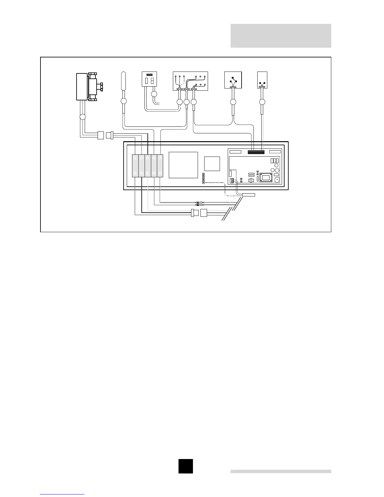
Fig. 18 Electrical drawing Selecta system boiler (use in conjunction with hydraulical
drawing Fig. 15)
pdf
Legend
OS = outside sensor (optional)
FS = 3 amp permanent fused supply via boiler 3 core cable fly lead (not supplied)
HS = hot water sensor
FL = to boiler fly lead
TC = external time clock with volt free switching (not supplied)
RT = room thermostat (not supplied)
ER = boiler earth terminal
ET = kit No. 1 electrical terminals
IP = rear view of boiler instrument panel
* = connect to same coloured cables located within boiler casing
Note: The heating and hot water switching must be volt free