Remeha Selecta
8
1
2
3
4
5
6
7
8
9
19
18
17
16
15
14
13
12
11
10
20
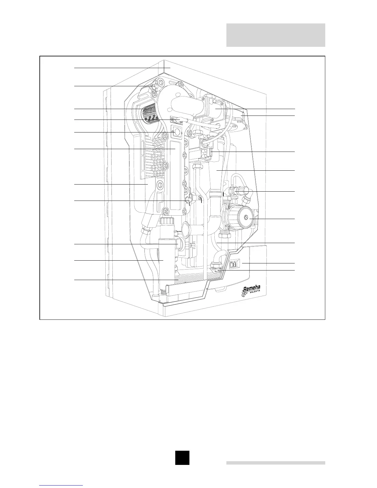
Fig. 02 Boiler layout Selecta (combi illustrated)
pdf
1. Venturi
2. Fan
3. Gas combi block
4. Air inlet tube
5. Safety valve
6. Pump
7. Expansion vessel
8. Instrument panel
9. Flow temperature sensor
(DHW; combi boiler only)
10. Plate heat exchanger
(combi boileronly)
11. Siphon / condensate outlet
12. 3-Way valve (combi boiler only)
13. Temperature sensor return
14. Heat exchanger
15. Heat exchanger inspection cover
16. Inspection glass
17. Combined ignition/ ionisation probe
18. Burner
19. Temperature sensor flow
20. Flue outlet / air inlet (60/100 mm; on
top, not visable in this picture)