RH850/U2A 292pin 1. Overview
R20UT4970ED0101 Rev.1.01 Page 12 of 67
July 08, 2022
1.7 Difference from Y-RH850-U2A-292PIN-PB-T1-V1 to Y-RH850-U2A-292PIN-PB-
T1-V2
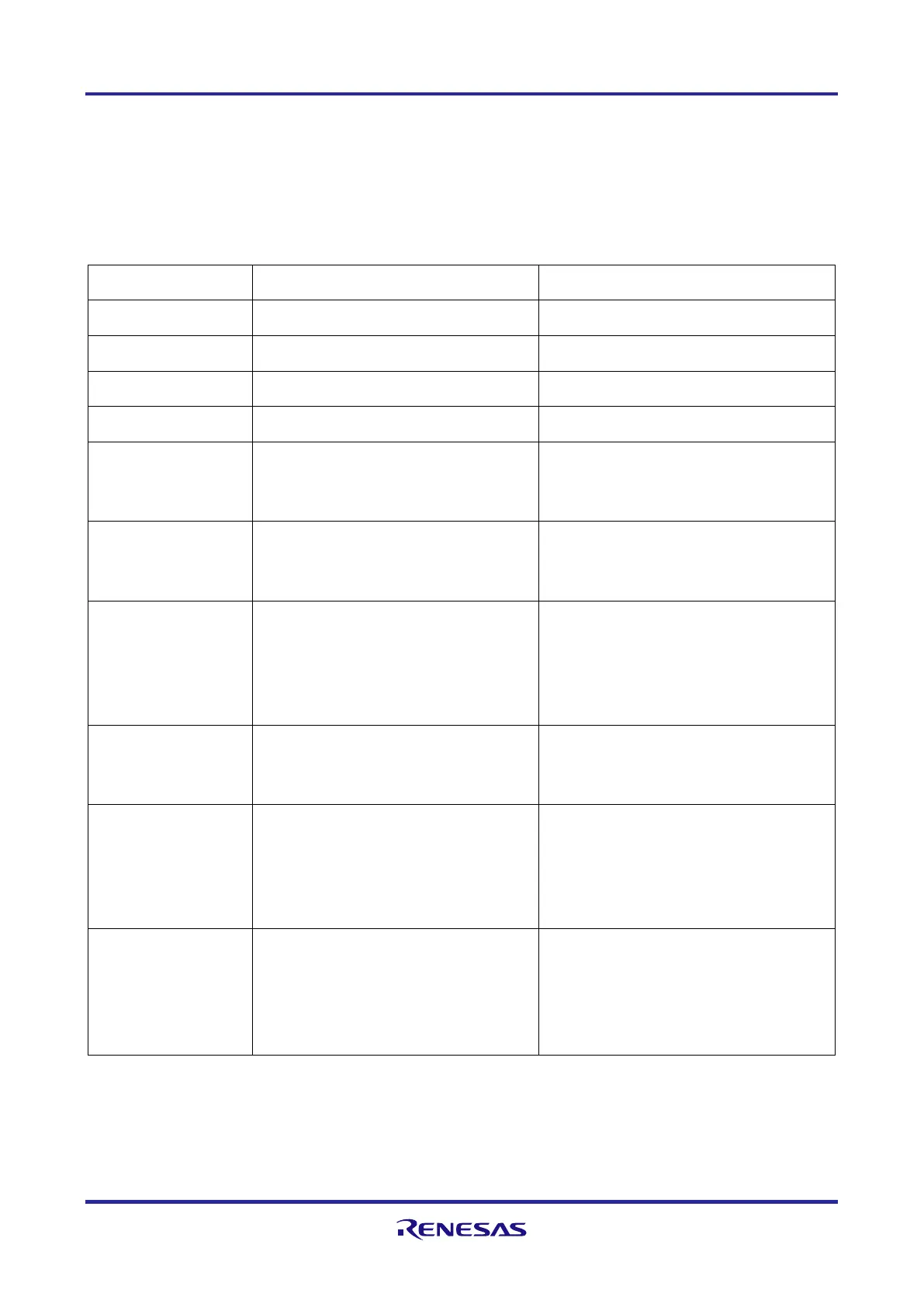
Several changes have been applied to the new version of the 292pin RH850/U2A piggyback
board compared to the first version. The table below summarizes all modifications.
Table 1.2 Difference between Y-RH850-U2A-292PIN-PB-T1-V1 and Y-RH850-U2A-292PIN-PB-T1-V2
Y-RH850-U2A-292PIN-PB-T1-V1
Y-RH850-U2A-292PIN-PB-T1-V2
capacitors C41
and C44
transceiver and bridges RB3/RB4
Placed between RH850/U2A and
bridges RB3/RB4
capacitors C41,
C44, C47, C48
Uses 100 Ohm resistor to connect
RX_DATA_N and RX_DATA_P
The pcb provides soldering points
to add a resistor between
RX_DATA_N and RX_DATA_P,
but by default this resistor is not
fitted.
AWOVCL
Both pins are directly connected
to AWOVCL on the board.
A18 is connected to AWOVCL via
100 Ohm resistor. A18 and P12 are
connected to VSS.
GETH0VCL
Connected directly to GETH0VCL
on the board.
Connected to GETH0VCL via 100
Ohm resistor and has a 220nF
capacitor to VSS. Provides the
possibility to connect pin E17 to
VSS via solder bridge RB5.
RH850/U2A8
RH850/U2A8
RH850/U2A6 (see
1.6
Modifications for U2A6 device
)

 Loading...


