RH850/U2A 292pin 7. Connectors
R20UT4970ED0101 Rev.1.01 Page 34 of 67
July 08, 2022
7. Connectors
7.1 Connectors to the Main Board CN1 to CN3
Three connectors (CN1 to CN3) are available to connect the piggyback board to a Main Board.
The signals of each connector are summarized in the following tables.
Note
Regarding the function on the Main Board, please refer to the User's Manual of any supported Main Board.
Refer to 1.2 Supported Main Boards for a list of supported Main Boards.
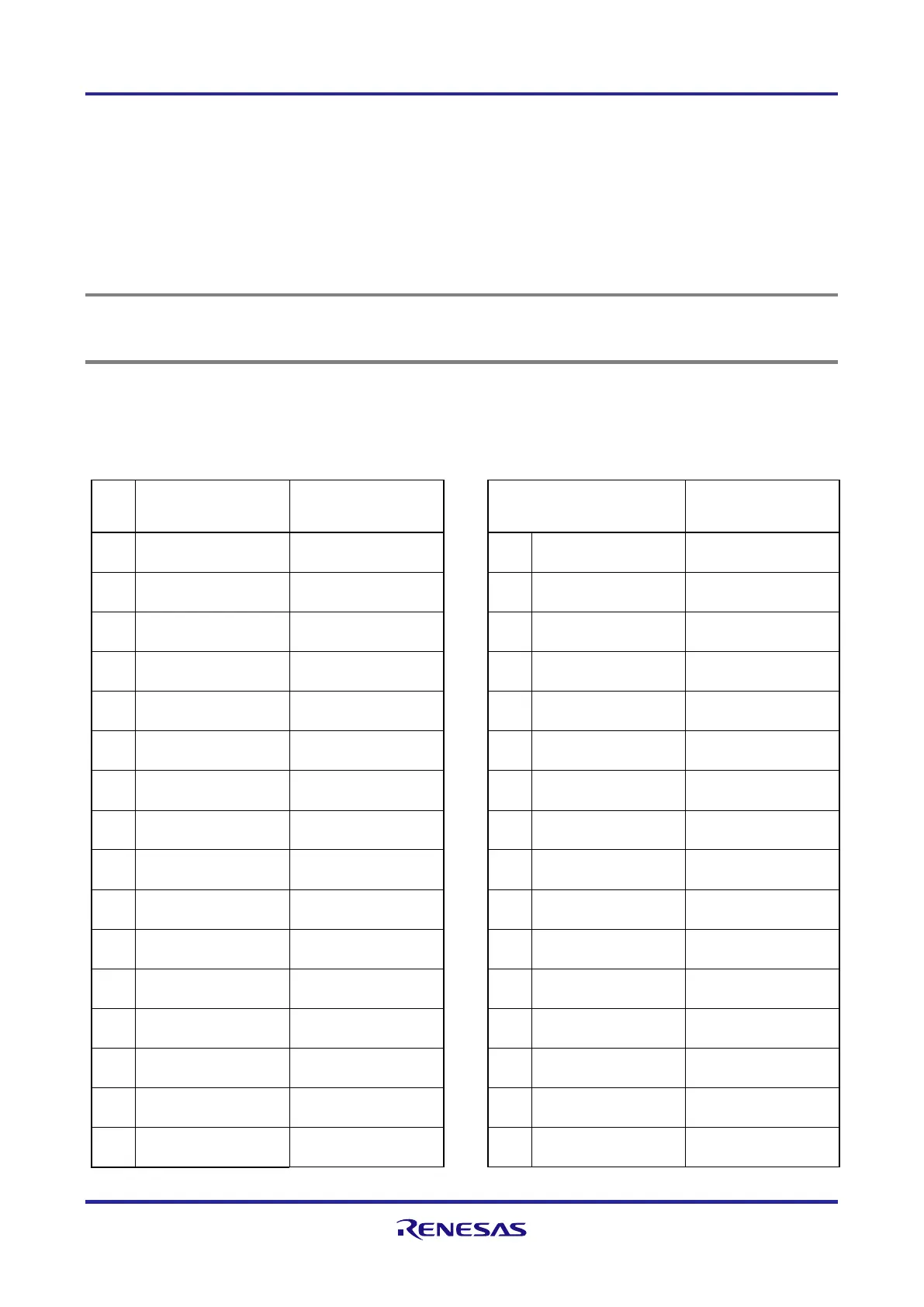
7.1.1 Main Board Connector CN1
Table 7.1 Main board connector CN1 (cont'd)
Pin Main Board function Piggyback board
device port
Pin Main Board function Piggyback board
device port
1 VDDA ‒ 2 VDDA ‒
3 VDDA ‒ 4 VDDA ‒
5 RESET RESETZ 6 NMI P4_7
7 WAKE ‒ 8 ‒ ‒
9 INT0 P10_12 10 INT1 P22_0
11 INT2 P21_7 12 INT3 P2_8
13 ‒ ‒ 14 ‒ ‒
15 UART0TX P6_6 16 UART1TX P6_3
17 UART0RX P6_5 18 UART1RX P6_2
19 LIN0TX P4_8 20 LIN1TX P2_5
21 LIN0RX P4_9 22 LIN1RX P2_4
23 IIC0SCL P17_3 24 IIC1SCL P22_4
25 IIC0SDA P17_2 26 IIC1SDA P22_3
27 CAN0TX P6_14 28 CAN1TX P6_8
29 CAN0RX P6_13 30 CAN1RX P6_7
31 SENT0RX P21_1 32 SENT1RX P21_0

 Loading...


