Home
Renesas
Computer Hardware
RH850
Renesas RH850
67 pages
Manual
To Next Page
To Next Page
To Previous Page
To Previous Page
Loading...
RH850/U2A
292pin
1
.
Overvi
ew
R20UT4970ED0101
Rev.1.01
Page
8
of
67
July 08, 2
022
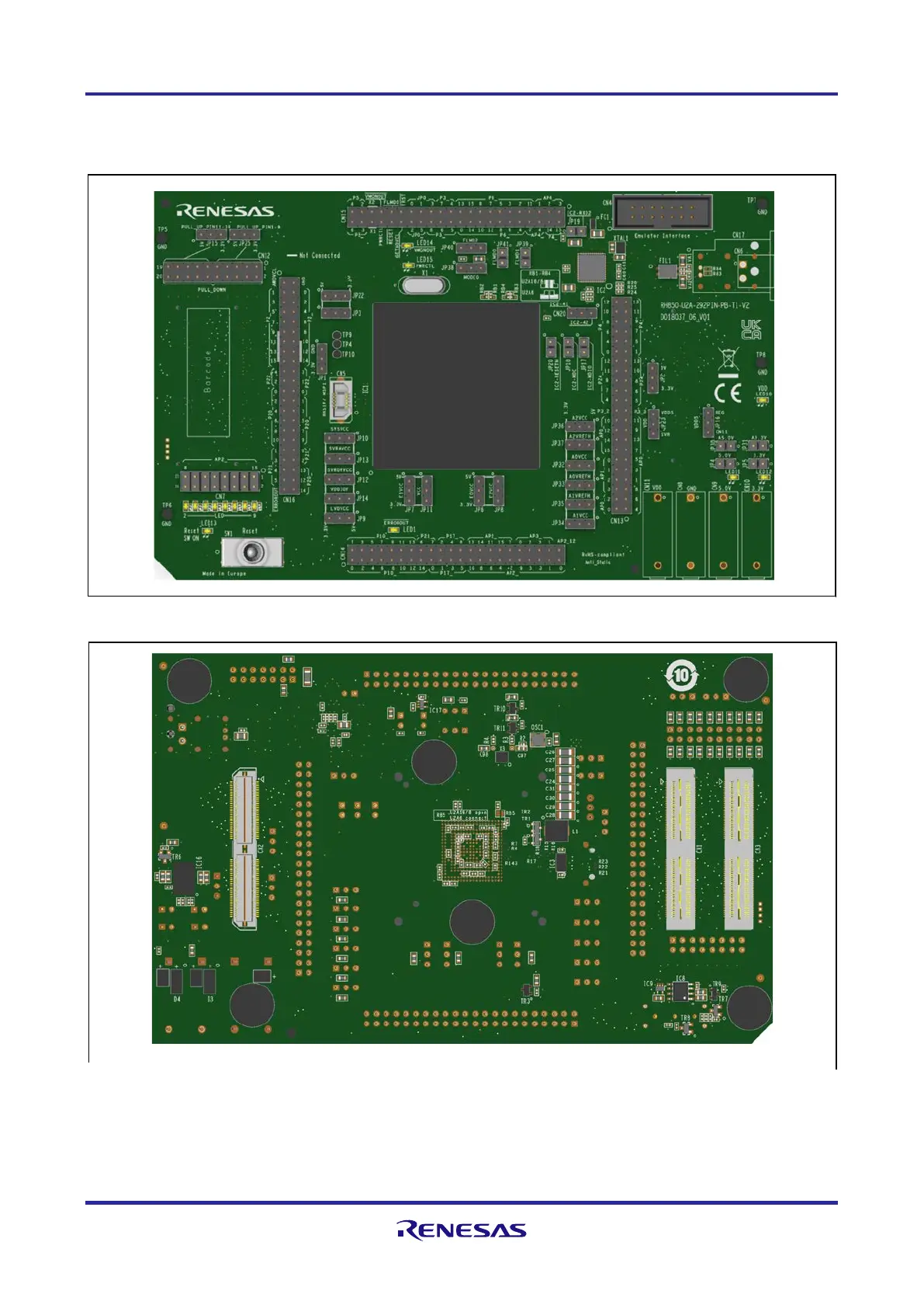
1.4
Piggy
b
ack Board
V
iews
Following figure
s
provi
de the top an
d bottom views o
f the
piggyback board
.
Figure
1.2
Piggy
b
ack
b
oard bottom
view
Figure
1.1
Piggyback board top vie
w
7
9
Table of Contents
Main Page
Table of Contents
4
Overview
6
Package Components
6
Supported Main Boards
7
Main Features
7
Piggyback Board Views
8
Mounting of the Device
10
Modifications for U2A6 Device
11
Difference from Y-RH850-U2A-292PIN-PB-T1-V1 to Y-RH850-U2A-292PIN-PB-T1-V2
12
Jumpers, Connectors and Leds
13
Jumpers Overview
13
Connectors Overview
19
LED Overview
20
Power Supply
21
Board Power Connection
21
Voltage Distribution
22
Device Core Voltage (VDD) Selection
24
Current Measurement Bridges
24
Power Supply Leds
25
Clock Supply
26
Main Oscillator
26
Programmable Oscillator
27
X1 and X2 on CN15
27
Debug and Flash Programming Interfaces
28
Other Circuitry
29
Operation Mode Selection
29
RESET Switch
30
Signaling Leds
30
Pull-Up/Pull-Down Pin Header
30
Automotive Ethernet Interface
31
Renesas High-Speed Serial I/F (RHSIF) / Multichannel Serial Peripheral Interface (MSPI)
33
Connectors
34
Connectors to the Main Board CN1 to CN3
34
Main Board Connector CN1
34
Main Board Connector CN2
37
Main Board Connector CN3
39
Debug Connector CN4
42
RHSIF/MSIP Connector CN5
42
Device Ports Connectors CN13 to CN16
43
Device Ports Connector CN13
44
Device Ports Connector CN14
45
Device Ports Connector CN15
46
Device Ports Connector CN16
47
Pull-Up/Pull-Down Pin Header CN12
48
Ethernet Connector CN6 and CN17
48
GPIO/LED Connector CN20
49
Jumper Configuration Examples
50
Stand-Alone Operation with Power Supply by Debugger
50
Configuration Examples
51
General Settings
51
Jumper Indicators
51
Stand-Alone Operation with Single External Power Supply: Minimum Configuration
52
Stand-Alone Operation with All External Power Supplies: Maximum Configuration
53
Operation on the Main Board: no External Supply
54
Precautions
55
Power-Off Sequence
55
CAN0RX Is Shared with FLASH Programmer Signal FLMD1
55
Deepstop Mode When Using SVR
55
Mechanical Dimensions
56
Schematics
57
Related product manuals
Renesas RH850/F1KM-S4
26 pages
Renesas RH850/U2A 292pin
58 pages
Renesas RX66T
25 pages
Renesas RZ/T2M
87 pages
Renesas RL78/G13
1092 pages
Renesas RL78/F13
1879 pages
Renesas RL78/F14
1879 pages
Renesas EK-RA6M3
41 pages
Renesas RL78/D1A
59 pages
Renesas RL78/G1D
59 pages
Renesas RZ Series
83 pages
Renesas RZ/A Series
106 pages

 Loading...


