RZ/A2M SUB Board RTK79210XXB00000BE 2. Function specifications
R20UT4398EJ0100 Rev.1.00 2-15
2018.10.11
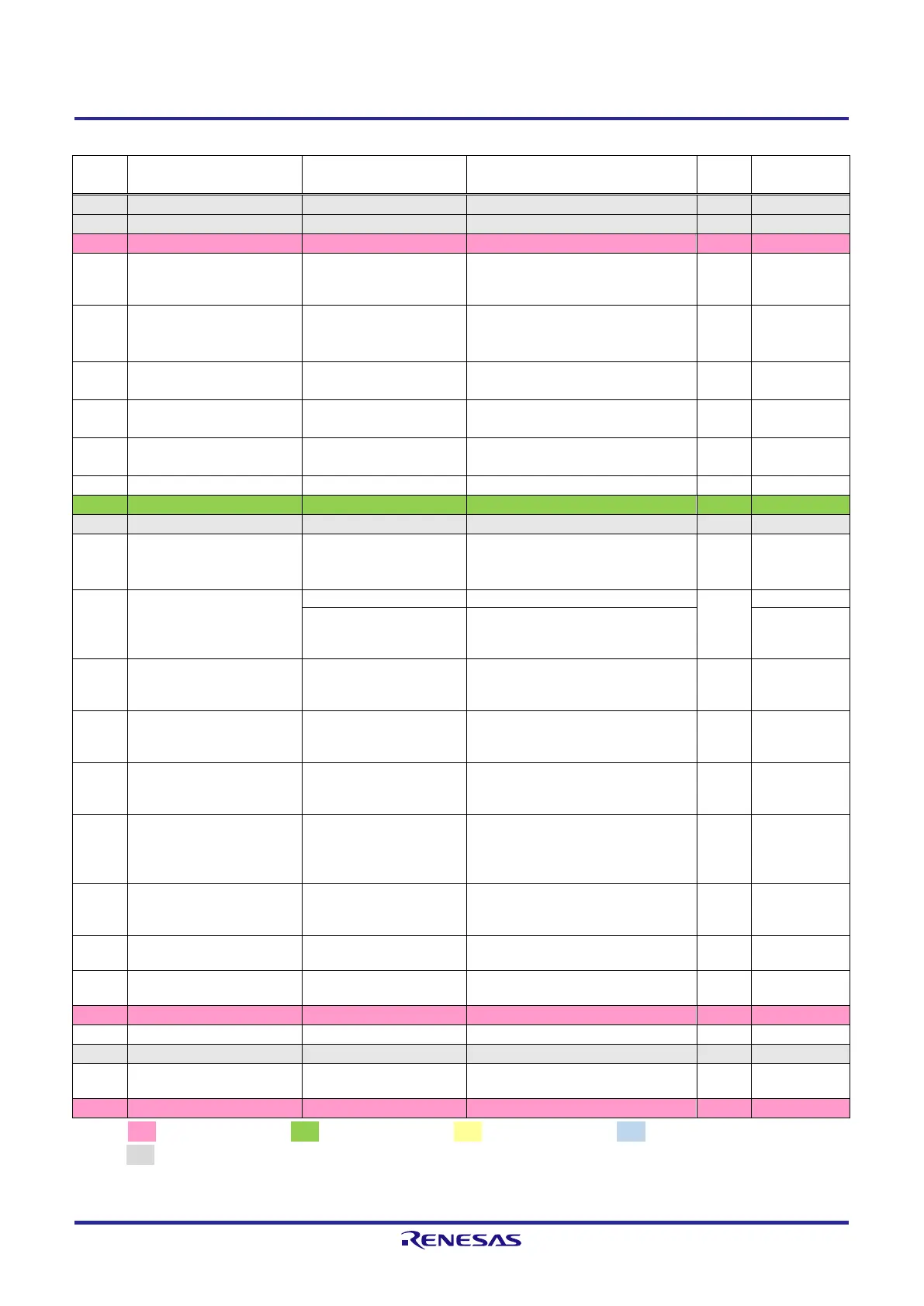
Table 2.2.14 List of RZ/A2M Pin Function Selections Used on the RTK79210XXB00000BE (14)
PC_7 / OVRCUR0 / FRB /
ET1_RXD3 / SD1_WP /
LCD0_TCON0 / IRQ6
Connects to USB VBUS power supply
control IC (U5 on the CPU board)
PC_6 / VBUSEN0 / FWE /
ET1_RXD2 / SD1_CD /
LCD0_TCON1 / IRQ7
Connects to USB VBUS power supply
control IC (U5 on the CPU board)
P5_0 / AN000 / IRQ4 /
SD0_CD / SD1_CD
Connects to microSD card slot (CN1
on the CPU board)
P5_1 / AN001 / IRQ5 /
SD0_WP / SD1_WP
Connects to D 3.3V and GND through
resistors
Connects to digital image input/output
connector (CN15)
Connects to SD card slot (CN10)
P1_1 / D8 / MTIOC8A /
IRQ1 / CAN0RX /
OVRCUR0
P3_4 / ET1_MDIO / FRB /
CC2_RA1 /
CAN1TX_DATARATE_EN /
SSL20
Connects to Ethernet PHY2 (U28)
Connects to NAND flash memory
(U31)
P3_0 / OTG_EXICEN1 /
NAF4 / ET1_LINKSTA /
MTIC5W / IRQ3
Connects to Ethernet PHY2 (U28)
PC_1 / VBUSIN0 / NAF6 /
ET1_TXD2 / MOSI2 /
LCD0_TCON6
Connects to LED1 (green) on the CPU
board
P4_0 / SCK0 / TXOUT0P /
SCI_SCK1 / SSIBCK1 /
MTIOC8A / IRQ0
Connects to LVDS connector (CN14)
P4_4 / CTS0 / TXOUT2P /
SCI_CTS0/RTS0 /
WDTOVF/PERROUT /
OTG_EXICEN0
Connects to LVDS connector (CN14)
P4_7 / ET0_WOL /
TXCLKOUTM / SCI_SCK0 /
SCK4 / TEND0
Connects to LVDS connector (CN14)
Connects to USB oscillator (X2 on the
CPU board)
Connects to USB connector (CN3 on
the CPU board)
Connects to GND through a resistor
Connects to USB Type-A port (CN12)
and USB Mini-B port (CN13)
[Note] : 3.3V power source, : 1.8V power source, : 1.2V power source, : 3.3V or 1.8V power source,
: GND
Red text CPU board setting display.
 Loading...


