RZ/A2M SUB Board RTK79210XXB00000BE 2. Function specifications
R20UT4398EJ0100 Rev.1.00 2-16
2018.10.11
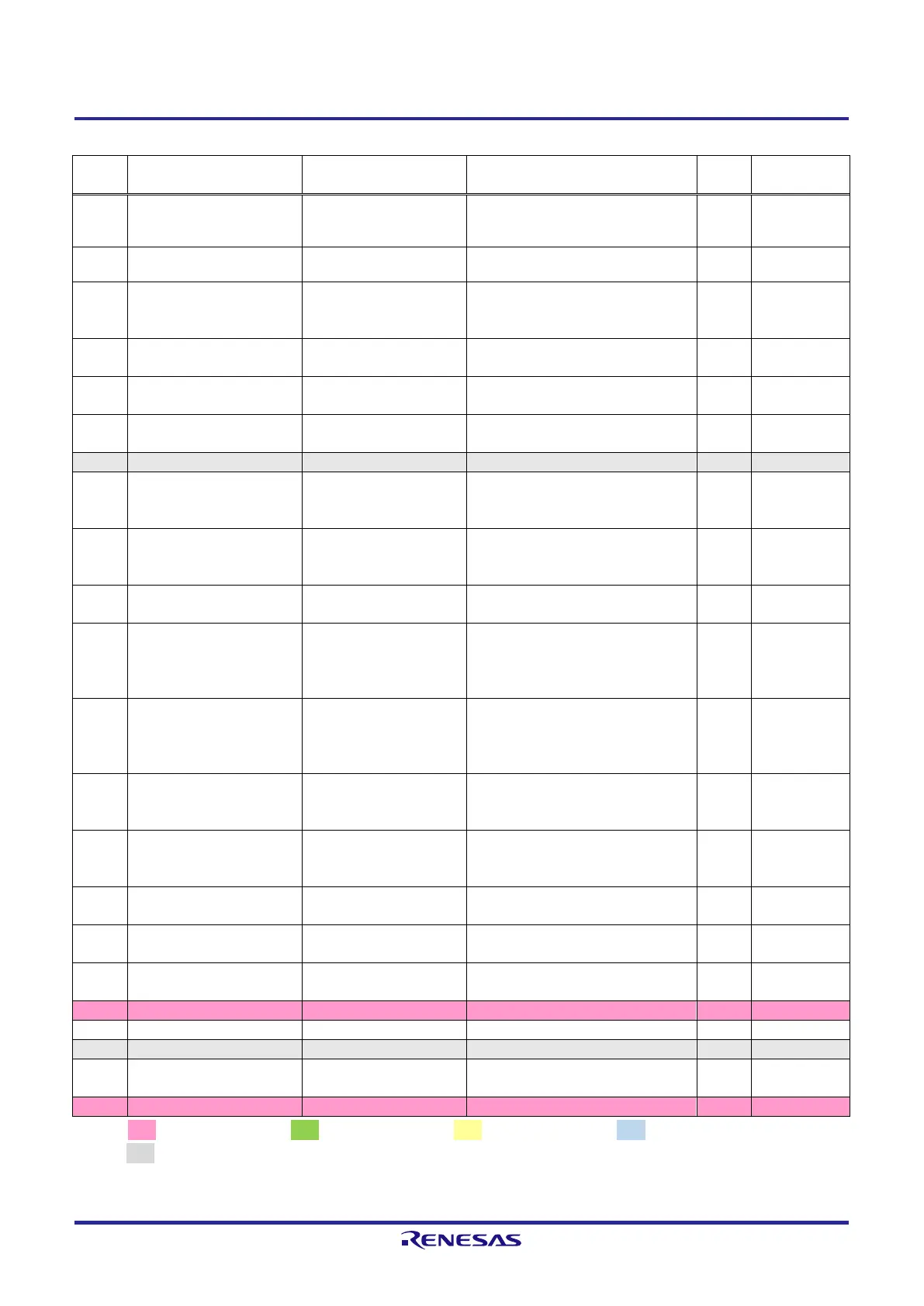
Table 2.2.15 List of RZ/A2M Pin Function Selections Used on the RTK79210XXB00000BE (15)
PC_5 / VBUSEN1 / FRE /
ET1_RXDV / SPDIF_OUT /
LCD0_TCON2 / IRQ0
Connects to USB Mini-B port (CN13)
Connects to system clock oscillator
(X1 on the CPU board)
PC_4 / OTG_ID1 / FALE /
ET1_TXER / SPDIF_IN /
LCD0_TCON3 / IRQ1
Connects to digital image input/output
connector (CN15)
Connects to RTC oscillator (X3 on the
CPU board)
P5_3 / AN003 / IRQ7 /
OTG_ID0
Connects to DIP switch (SW6)
P5_5 / AN005 / IRQ1 /
SD1_WP
Connects to SD card slot (CN10)
PG_5 / ET0_RXDV /
VIO_D14 / MOSI1 /
MTIOC4B / GTIOC1B
Connects to CMOS camera connector
(CN17)
PG_7 / ET0_RXD3 /
VIO_D12 / SSL10 /
MTIOC4D / GTIOC2B
Connects to CMOS camera connector
(CN17)
P1_3 / D10 / MTIOC8C /
IRQ3 / CAN0TX / OTG_ID1
P2_1 / D13 / GTIOC6B /
IRQ6 /
CAN1RX_DATARATE_EN /
OTG_ID0
P2_3 / D15 / GTIOC7B /
WDTOVF/PERROUT /
CAN1TX_DATARATE_EN /
OTG_EXICEN1
P4_1 / RxD0 / TXOUT0M /
SCI_RXD1 / SSIRxD1 /
MTIOC8B / IRQ1
Connects to LVDS connector (CN14)
P4_5 / ET0_LINKSTA /
TXOUT2M / SCI_RXD0 /
RxD4 / DREQ0
Connects to LVDS connector (CN14)
Connects to Reset input switch (SW2
on the CPU board)
Connects to USB oscillator (X2 on the
CPU board)
Connects to USB connector (CN3 on
the CPU board)
Connects to GND through a resistor
Connects to USB Type-A port (CN12)
and USB Mini-B port (CN13)
[Note] : 3.3V power source, : 1.8V power source, : 1.2V power source, : 3.3V or 1.8V power source,
: GND
Red text CPU board setting display.
 Loading...


