en
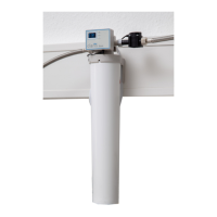
Test strips
German degrees (°dH) /
degree of General
Hardness (dGH)
< 3 > 4 > 7 > 14 > 21
English degrees
(Clark degrees) (°e)
< 3.75 > 5 > 8.75 > 17.5 > 26.25
French degrees
(°fH)
< 5.4 > 7.2 > 12.6 > 25.2 > 37.8
Parts per million
(ppm CaCO
3
)
< 53.4 > 71.2 > 125 > 249 > 374
Blend level
3 3 2 2 1
Capacity
Filter cartridge M in
liters
3570 3060 1440 990 510
Capacity
Filter cartridge L in
liters
6670 5710 2690 1840 940
4.4 Assembling the lter head / owmeter / lter cartridge
TheowmeterforthePOWERsteamerwatersoftenerconsistsofthefollowingcomponents:
• Sensor unit
• Programming and display unit
Assembly of the product comprises the following steps:
• Assemblyofthelterhead.
• Assembly of the sensor unit�
• Connection to the water supply and to the POWER steamer 2�
• Assemblyoftheltercartridge.
• Assemblyandconnectionoftheprogramminganddisplayunit(Chap.4.5).
⇒ Disconnect the POWER steamer 2 from the power source�
⇒ TurnothewatersupplytothePOWERsteamer2anddisconnectthewaterhosetothePOWER
steamer 2 from the water supply�
⇒ Securelyattachthelterheadtoawallinaverticalpositionusingappropriatescrews(notincludedin
thescopeofdelivery).
Theltersystemcanalsobeoperatedeitherfree-standingoronitssidewithoutbeingsecured.
Vertical wall mounting is recommended.
When assembling the sensor unit, the adapter and the water hoses, make sure that you use the
corresponding gaskets.
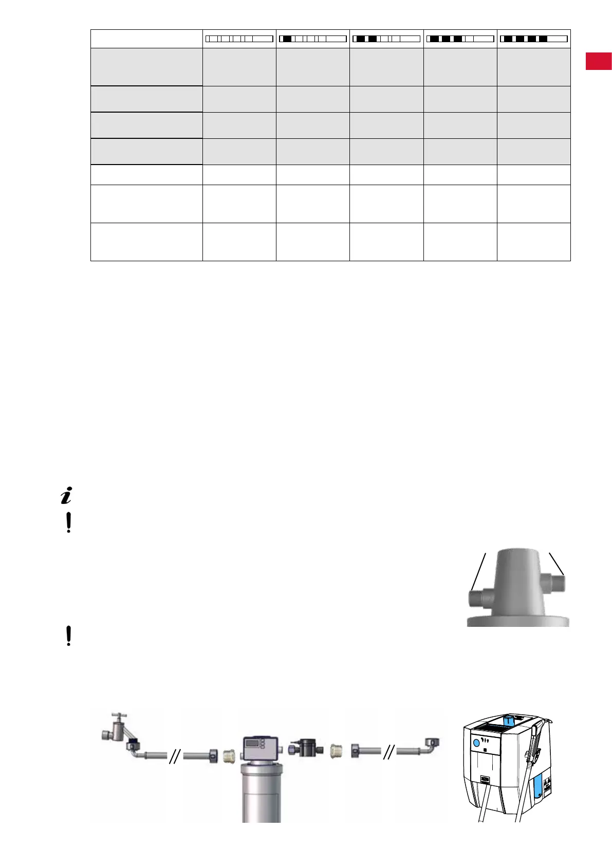
⇒ Screwoneadapter(3/4"-3/8")ontotheconnectionofthesensorunit
(10,Fig.1).
⇒ Screwoneadapter(3/4"-3/8")ontotheinletofthelterhead(3).
⇒ Screwthesensorunittotheoutletofthelterhead(4)usingtheunionnut.
⇒ Connect the water hose for the POWER steamer 2 to the adapter of the sen-
sor unit�
The sensor unit must not be exposed to any mechanical loads.
⇒ Connectthewaterhoseprovidedtotheadapterattheinletofthelterhead
and to the water supply�
⇒ Notetheowdirection–markingsonthelterheadandsensorunit!
⇒ Max� torque 10 Nm�
Fig. 4: Typical installation example
4
Fig.
3
Fig.
43
- 7 -
 Loading...