en
Only use the hoses provided.
Do not use hoses or adapters with conical screw connections. They will damage the connections
and cause the warranty to be voided.
When using screw adapters:
Only use matching screw adapters of a suitable length. When screwing on, do not place them axi-
ally on the lter head. Unsuitable adapters can damage the connections and cause the warranty to
be voided.
⇒ Runtheushinghoseintoasuitablecontainer(e.g.,abucket)orintoa
drain�
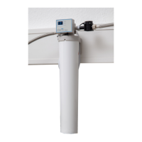
⇒ Openthepurgevalve(5)(OPEN).
⇒ Turn on the water supply�
⇒ Inserttheltercartridgeintothelterhead.
InserttheltercartridgewithitsmarkingatinsertionmarkAandscrew
itinasfarasitwillgo,operatingmarkB.
♦ Insertingtheltercartridgeventsthesystemandushestheltercar-
tridge:
- Filter cartridge M: Flush with min� 5 liters of water
- Filter cartridge L: Flush with min� 10 liters of water
⇒ Closethepurgevalve(CLOSE).
⇒ Aftertheinitialinstallationoftheltersystem,ventandushthewaterdrain
hose and the POWER steamer 2 with at least 2 liters of water� To do this,
open the service opening on the POWER steamer 2 and run the rinsing
program3times(seeoperatinginstructionsforthePOWERsteamer2).
After installing the system and inserting or replacing a lter cartridge,
check all components for leak-tightness. Water must not leak out at any
location.
4.5 Programming and display unit
Theprogramminganddisplayunitcaneitherbeattachedtotheheadofthelterunitusingthehold-
er(11,Fig.1)ortoawallusingthewallbracketprovided(12,Fig.1).
Attachment to the head using the holder (11, Fig. 1):
⇒ Push the holder onto the head unit until it snaps into place�
⇒ Open the battery compartment and insert batteries, 2 x type AA�
⇒ Pay attention to correct polarity�
⇒ Hang the programming and display unit in the holder�
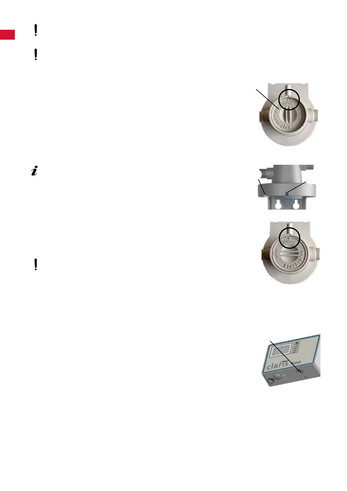
⇒ Insert the connection cable of the sensor unit into the port on the program-
minganddisplayunit(20).
5
B
A
20
- 8 -
 Loading...