OMP40-2 installation guide
2.2
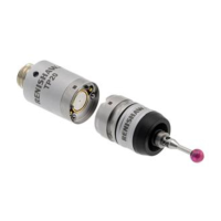
OMP40-2 basics
System interface
The interface conveys and processes signals between the probe and CNC machine controller.
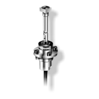
OMM-2 or OMM-2C receiver with OSI or OSI-D interface or OMI-2 / OMI-2T / OMI-2H / OMI-2C
receiver / interface (modulated transmission)
The OMI-2T receiver / interface or OMM-2 receiver with OSI or OSI-D interfaces are the recommended
interfaces for use with the OMP40-2 as they provide substantially increased resistance to light
interference whilst providing the user greater flexibility to operate a multiple probe system.
OMI receiver / interface or OMM receiver with MI 12 interface (legacy transmission)
Alternative interfaces are the OMI receiver / interface or OMM receiver with the MI 12 interface.
Trigger Logic™
Trigger Logic™ (see Section 4, “Trigger Logic™”) is a method that allows the user to view and select
all available mode settings in order to customise a probe to suit a specific application. Trigger Logic is
activated by battery insertion and uses a sequence of stylus deflections (triggering) to systematically
lead the user through the available choices to allow selection of the required mode options.
A Probe setup app is available that simplifies this process with clear, interactive instructions and
informative videos and is available for download on the App Store and Google Play.
or
Current probe settings can be reviewed by simply removing the batteries for a minimum of 5 seconds,
and then replacing them to activate the Trigger Logic review sequence (see page 4.1, “Reviewing the
probe settings”, for further information).
Probe modes
The OMP40-2 probe can be set in one of three modes:
Standby mode – probe is waiting for a switch-on signal.
Operational mode – when activated by one of the switch-on methods described later in this section.
The probe is switched on and ready for use.
Configuration mode – where Trigger Logic may be used to configure the following probe settings.
NOTE: A visual indication of currently selected probe settings is provided on battery insertion, by the
three multicolour LEDs located within the probe window (see Section 4, “Trigger Logic™”).