57 XL80 laser system
Linear
XL-80 Hardware
XL-80 Applications
Angular
Straightness
www�renishaw�com/xl80
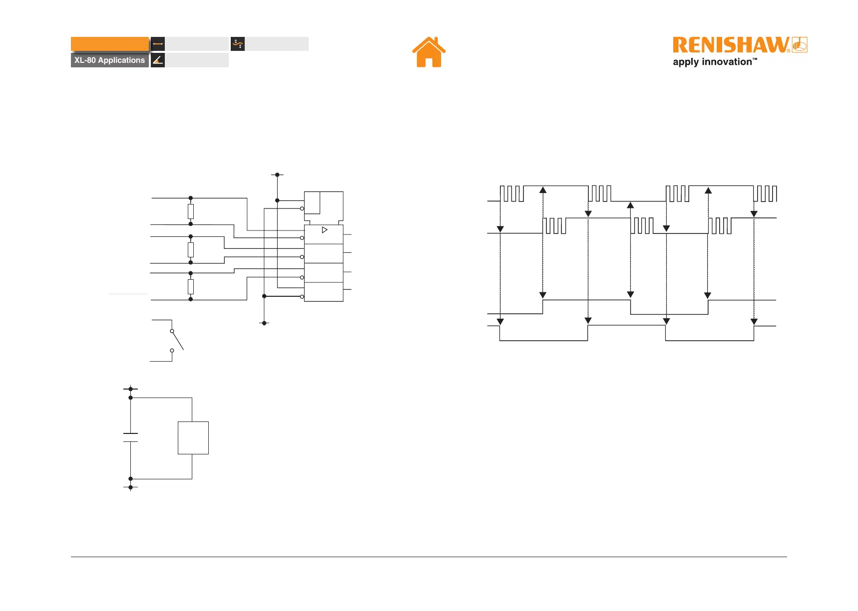
RS422 receiver circuitry
The image below shows a recommended circuit for the user end of RS422
receivers� A, B and ALARMOUT signals should be DC terminated with a 100
W to 120 W resistor�
100R
100R
100R
ALARMOUT
A
__
A
B
__
B
ALARMOUT
DATUM
SWITCH
4
12
2
1
6
7
10
9
14
15
0
V
0
V
EN
=1
IC1
AQUAD
BQUAD
ERTIN
3.3 V
10 nF
16
8
0
V
IC1
Hysteresis disabled
Hysteresis enabled
AQuad
AQuad
BQuad
BQuad
Figure 6 IC1 = MAXIM MAX3096
Recommended RS422 receiver
Hysteresis
Electrical noise or axis vibration can cause multiple edges to appear at each
quadrature transition as shown below, even when stationary�
If a fast counter is not available, hysteresis may be applied (DIP switch 3 on),
to clean up the edges so that only a single transition occurs each time� Note
this will introduce one unit of resolution (10 nm / 80 nm) positional hystersis
when the direction of travel is reversed�
XL-80 Hardware
 Loading...