Introduction
41
Doc No: UMAN\FL\0110
Rev. No.: 1.02B
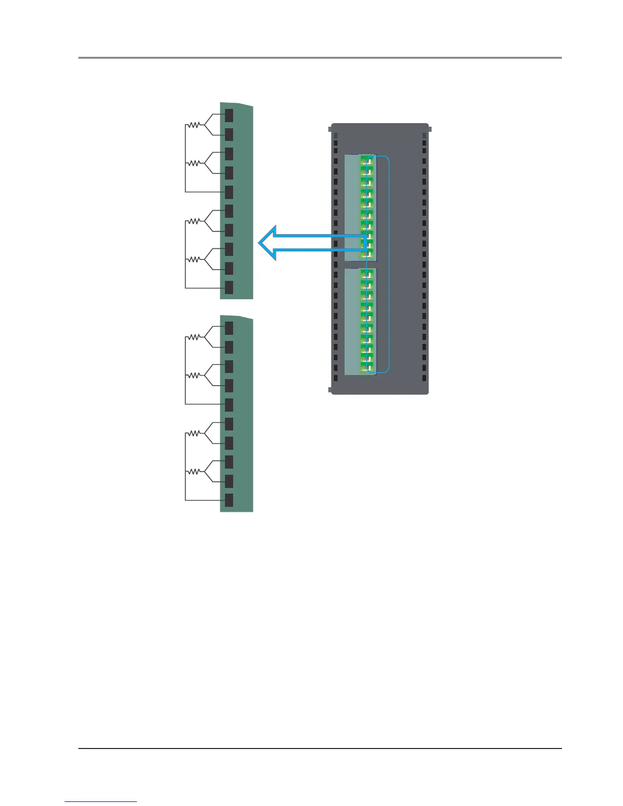
Wiring Diagram of input connection for FLA0800R:
PWR
F
L
A
0
8
0
0
R
CS1
CS3
AIN1
AIN3
CS2
CS4
AIN2
AIN4
AGND
AGND
CS5
CS7
AIN5
AIN7
CS6
CS8
AIN6
AIN8
AGND
AGND
RTD
PT1000
Note:
CSx: Current source(x equals to 1 to 8)
AINx: Analog input(x equals to 1 to 8)
AGND: Analog ground.Analog ground for
all channels is internally shorted on PCB
Connect RTD PT100 as shown in the above
diagram between the points CS, AIN and AGND
CS1
CS3
AIN1
AIN3
CS2
CS4
AIN2
AIN4
AGND
AGND
CS5
CS7
AIN5
AIN7
CS6
CS8
AIN6
AIN8
AGND
AGND
Input Channel 0
Input Channel 1
Input Channel 2
Input Channel 3
Input Channel 4
Input Channel 5
Input Channel 6
Input Channel 7