Hardware
56
Doc No: UMAN\FL\0110
Rev. No.: 1.02B
2.8 Wiring Diagram
If wiring is to be exposed to lightening or surges, use appropriate surge suppression devices. Keep AC, high energy
and rapidly switching DC wiring separate from signal wires.
Connecting high voltages or AC power mains to the DC input will make unit unusable and may create an electrical
shock hazard to personnel. Such a failure or shock could result in serious personal injury, loss of life and/or equip-
ment damage. DC voltage sources should provide proper isolation from main AC power and similar hazards.
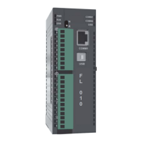
Pin description of the power connector for base (FL010 and FL050) models is as follows:
DC+ DC- Earth
24Vdc
123
2.9 Communication Ports
FlexiLogics communication ports support three types of serial communication.
They have two communication Ports in which COM1 is multi-signal port. Multi-Signal means COM1 port has RS232,
RS422, and RS485 signal levels.
A FlexiLogics can simultaneously communicate on both serial ports. The FlexiLogics can be programmed from a
PC on either port. Both ports can also be used with a serial printer.
Different cables are required to connect the FlexiLogics to a specific PLC. Cable details for any particular device are
given in the Operation Manual. The pin description of the communication ports for FlexiLogics model is as given
below:
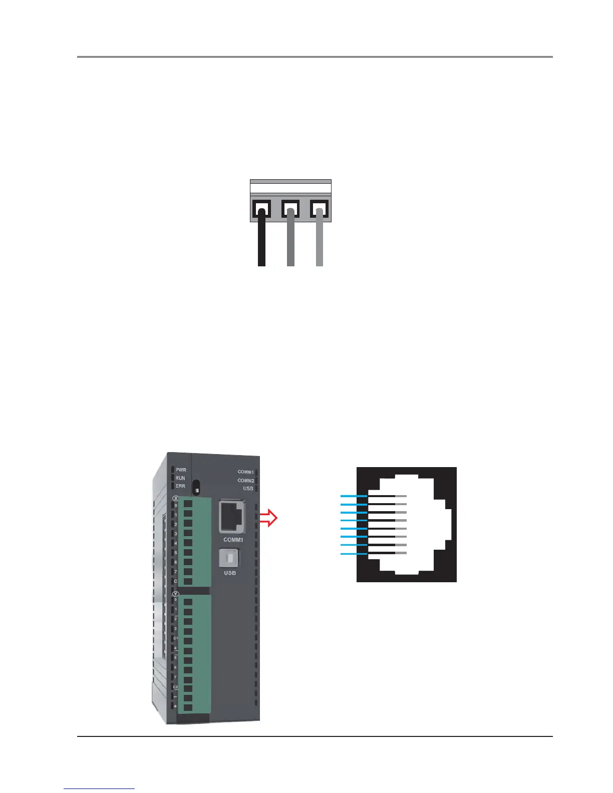
1. COM1 Port Details:
Pin 1: 232TXD
Pin 2: 232RXD
Pin 3: GND
Pin 4: TX+
Pin 5: RX+
Pin 6: TX-
Pin 7: RX-
Pin 8: Reserved
R
H
F
L
0
1
0