Hardware
55
Doc No: UMAN\FL\0110
Rev. No.: 1.02B
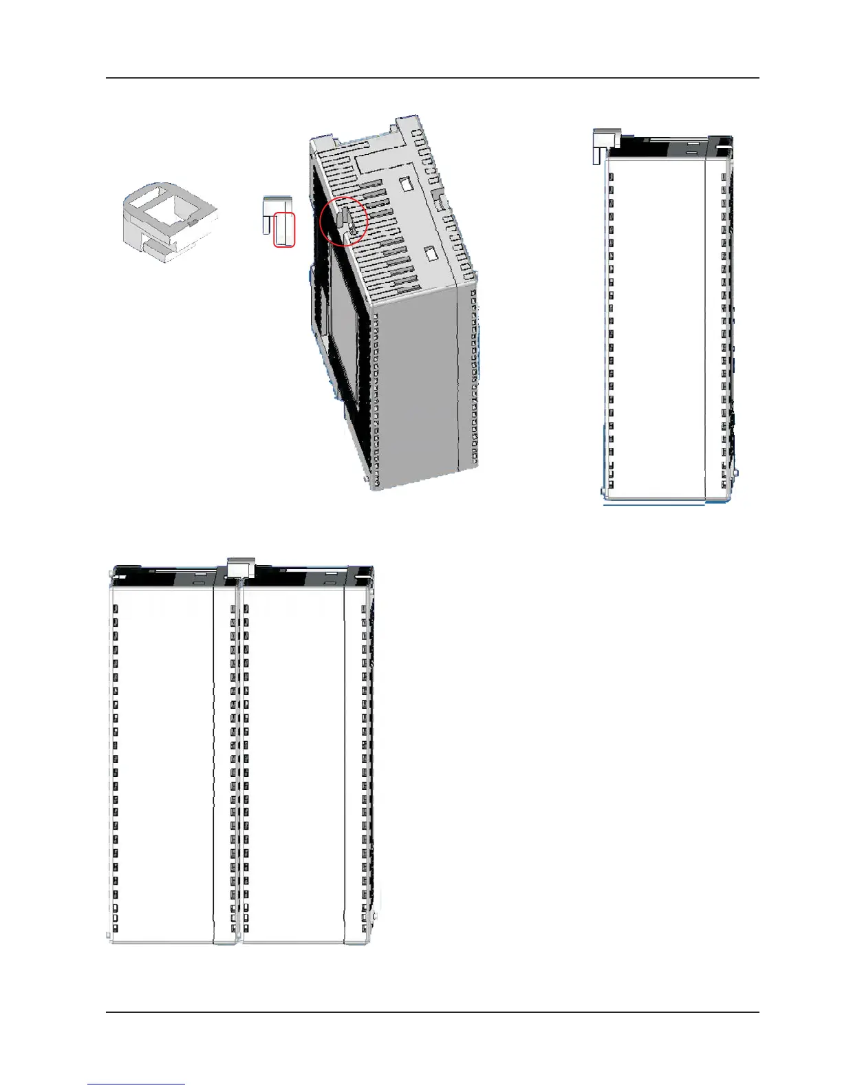
Steps to lock the expansion module with the FlexiLogics base
FIG-1 FIG-2 FIG-3
FIG-4
FIG-1 Lock connector provided with FlexiLogics unit
FIG-2 Two slots to grip the locking connector
are provided on the case highlighted by
RED circle. Insert a big leg of locking
connector highlighted by RED rectangle.
FIG-3 Single FlexiLogics unit with locking connector
FIG-4 Locking connector helps the two units
(FlexiLogics base & expansions)
to hold each-other properly on the DIN
rail plate along with DIN rail slider.
Note: Apart from these lockings, also expansion connec-
tor is present to each FlexiLogics unit. User can connect
FlexiLogics base to expansion unit using this connector.
Also user can add more expansions to the unit with this
connector only.