Chapter 3
Theory of Operation
REF 1029568 Rev B BiPAP Focus Ventilator Service Manual © Respironics, Inc. 3-5
3.2.1 User Interface PCB
The user interface PCB (Figure 3-3) includes:
• Motorola 68332 microcontroller
• Inter-processor communication with controller PCB
• VGA display, keyboard, and front panel LED interface
• Primary alarm driver
• Remote alarm relay
• USB and RS-232 serial communication
• Power supply input, monitoring, and distribution
• 18 VDC input voltage/primary working voltage
• 12 VDC-relay control and 3.3 and 5.5 supply sources
• 5 VDC - USB drivers, LCD display, CCFL inverter
• 3.3 VDC - kernel circuits, digital circuits
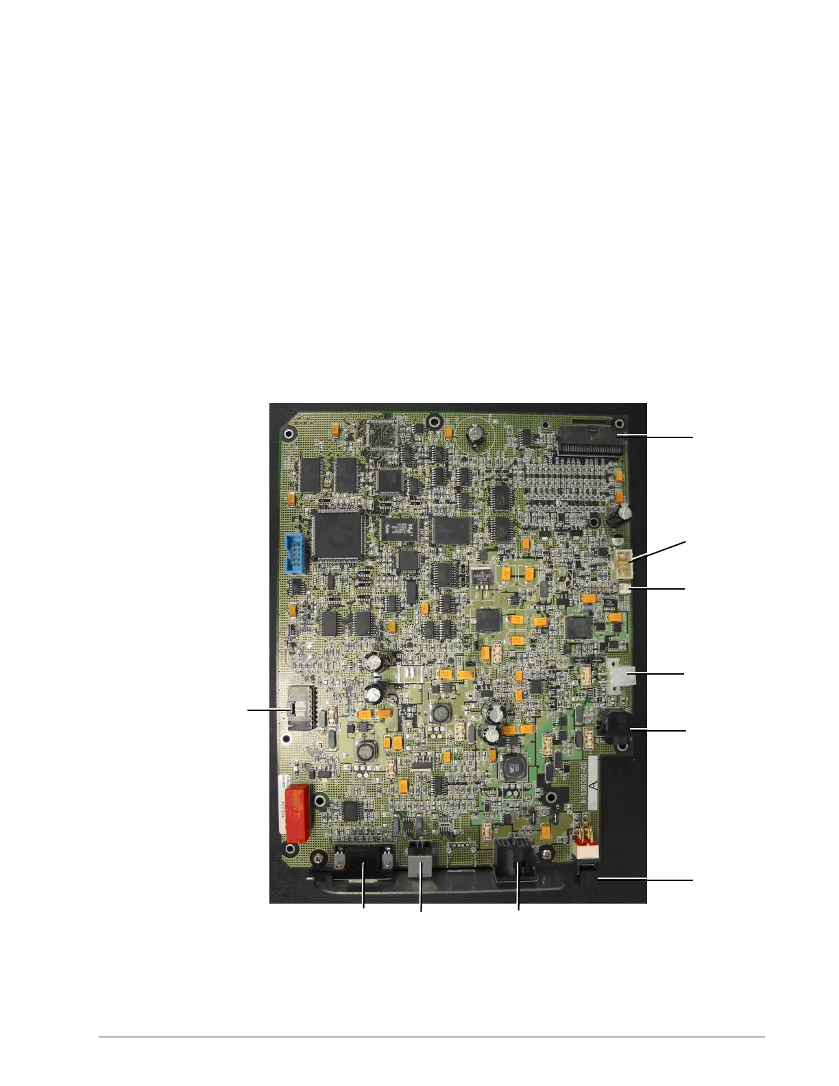
Figure 3-3: BiPAP Focus User Interface PCB
J1-interprocessor
communications
cable
Connects to J1
and J10 of the
controller PCB
S1
ON/OFF
switch
J10
interconnect
power cable
18 VDC to
controller PCB
J13
switch control
cable
J8
battery cable
J12
primary alarm
connector
J9
VGA/UI
ribbon
cable
J3
serial
port
J4
USB
port
J6
power supply
connection