REYMSA COOLING TOWERS, INC.
www.reymsa.com
4
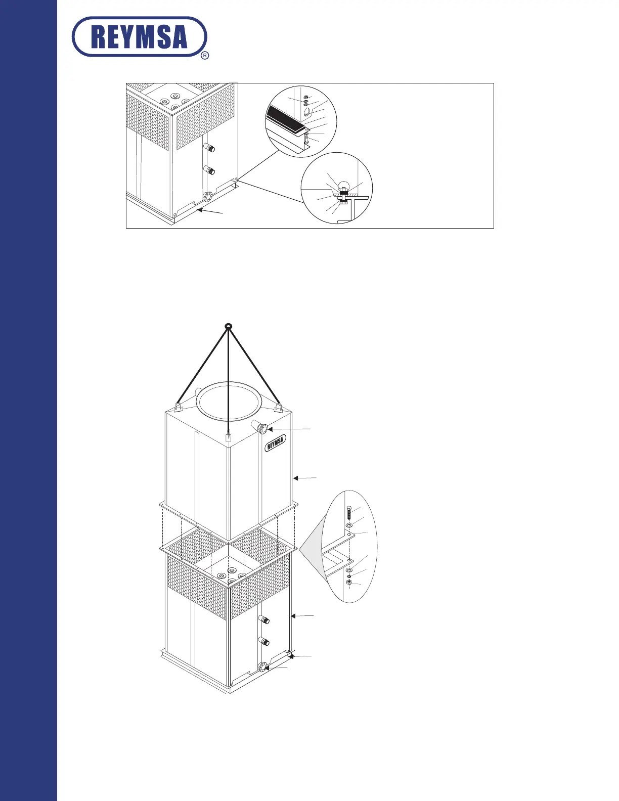
H. Assemble the upper section with the lower section, the upper section comes assembled with u-bolts for
lifting; then using a crane assemble both parts, use a guide pin to align bolt holes as the sections are being
set (See gure A-7). Make sure that the recirculation water inlet, and the recirculation water outlet are on
the same side of the tower when assembled.
2
3
4
5
6
1
RECIRCULATION WATER INLET
UPPER SECTION
ASSEMBLY HOLES
1. 1/2” x 2.5” BOLT
2. 1/2” FLAT WASHER
3. 5/8 HOLE
4. 1/2 FLAT WASHER
5. 1/2” LOCK WASHER
6. 1/2 NUT
(SUPPLIED BY OTHERS)
LOWER SECTION
RECIRCULATION WATER OUTLET
STEEL BASE STRUCTURE
(SUPPLIED BY OTHERS)
Figure A-7: Upper and lower parts installation
Installation
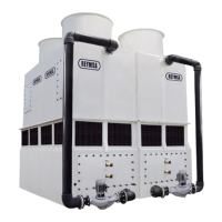
1
2
3
7
8
1
2
3
4
6
7
8
5
5
4 ANCHORAGE HOLES
(ONE ON EACH CORNER)
1. 3/4” NUT
2. 3/4” LOCK WASHER
3. 3/4” FLAT WASHER
4. 3/4” ANCHORAGE HOLES
5. ISOLATION PAD
6. ≈1” HOLE
7. 3/4” FLAT WASHER
8. 3/4” X 3” BOLT
(SUPPLIED BY OTHERS)
STEEL BASE SUPPORT
(SUPPLIED BY OTHERS)
Figure A-6: Typical anchorage for a single fan tower.