REYMSA COOLING TOWERS, INC.
www.reymsa.com
The
All-Fiberglass
Cooling Towers
55
Maintenance
D.8. COPPER COIL UNIT
The copper coil unit should be inspected annually or as needed, and cleaned as required.
Remove the service door(s) for copper coil(s) unit(s) access and unscrew bolts that support the coil, located at
either side, down on each slide-angle that supports the copper coil unit. Then, in case you are located on the
ground; place a forklift right in front of a lengthwise set of forks that totally cover the unit size. Should the
tower be in a roof area, use a mobile oor crane with the right load capacity, and a steel work table as an
hook device see Table D-4 for Copper Coil Unit(s) total weight by model. Finally pull the coil out carefully,
avoiding contact with tower body to prevent any damage. (See Figures D-1 and D-2 for reference.)
Place the cooper coil unit in a well lighted open room, and proceed as follows:
1. Blow compressed air across the coil, use a plastic brush to wash and remove the debris accumulated
out off the coil.
2. Use a pressure washer to spray fresh water and remove the silt, mud or slime for the coil.
3. The use of cleaning agents must follow the manufacturer’s directions for proper mixing and cleaning.
Verify there are no chemical residues still remaining in the coil after the cleaning process.
4. The rinsing process is important to avoid, the clean agent residue could initiate a corrosion process.
5. If the Closed Circuit Fluid Cooler is located in a very aggressive environment, periodic cleaning
process must be required.
Figure D-2: Copper coil unit pulled out
for maintenance purpose when tower is on the ground.
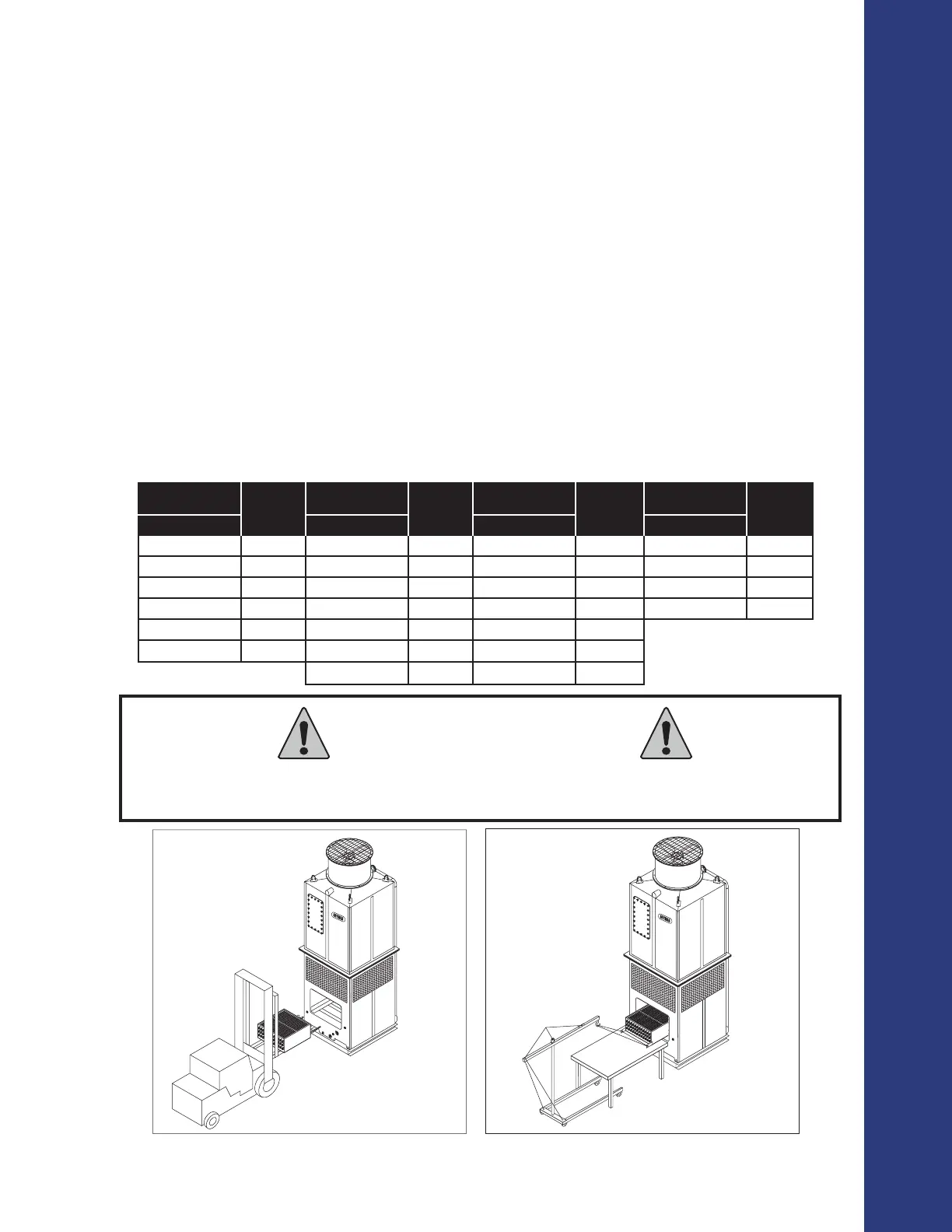
Figure D-3: Copper coil unit pulled out
for maintenance purpose when tower is on the roof.
The chemical treatment supply connection is not factory installed. This connection must be installed
on the basin (below the copper coil) to dilute the chemicals in the water. Direct exposure of the
copper coil to the chemicals may accelerate corrosion.
CAUTION
Tabla D-4: Copper coil unit(s) weight by model
HFC SINGLE FAN
(DIRECT DRIVE))
COIL
WEIGHT
(lbs)
HFC DOBLE FAN
(DIRECT DRIVE))
COIL
WEIGHT
(lbs)
HFC QUADRUPLE FAN
(DIRECT DRIVE)
COIL
WEIGHT
(lbs)
HFC SINGLE FAN
(GEAR DRIVE)
COIL
WEIGHT (lbs)
Model-Qty Coil Model-Qty Coil Model-Qty Coil Model-Qty Coil
505XXX- ONE COIL 620 510XXX- TWO COILS 620 1010XXX- FOUR COILS 620 1012XXX- FOUR COILS 1558
606XXX- ONE COIL 890 612XXX- TWO COILS 890 1212XXX- FOUR COILS 890 1016XXX- FOUR COILS 2148
707XXX- ONE COIL 1270 714XXX- TWO COILS 1270 1414XXX- FOUR COILS 1269 1216XXX- FOUR COILS 2193
808XXX- ONE COIL 1570 816XXX- TWO COILS 1570 1616XXX- FOUR COILS 1569 1218XXX- FOUR COILS 3218
810XXX- TWO COILS 1245 819XXX- FOUR COILS 1170 1619XXX- EIGHT COILS 1169
812XXX- TWO COILS 1378 822XXX- FOUR COILS 1280 1622XXX- EIGHT COILS 1279
827XXX- FOUR COILS 1450 1627XXX- EIGHT COILS 1451