REYMSA COOLING TOWERS, INC.
www.reymsa.com
10
STEEL BASE STRUCTURE
(SUPPLIED BY OTHERS)
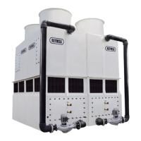
4 ANCHORAGE HOLES
(ONE ON EACH CORNER)
1. 3/4” NUT
2. 3/4” LOCK WASHER
3. 3/4” FLAT WASHER
4. 3/4” ANCHORAGE HOLES
5. ISOLATION PAD
6. ≈1” HOLE
7. 3/4” FLAT WASHER
8. 3/4” X 3” BOLT
(SUPPLIED BY OTHERS)
Figure A-21: Basin lifting (optional) Figure A-22: Typical anchorage for a double fan tower
I. Proceed to lift the Upper section 1 over the top of Lower section 1, making sure that the bolt holes on
Upper section 1 are aligned with the perforations on Lower section 1, then bolt down and secure the
horizontal anges with the stainless steel nut and bolt supplied by REYMSA. See gure A-24 (wait the nal
tight until two upper section are on place and you can tightened also the vertical anges).
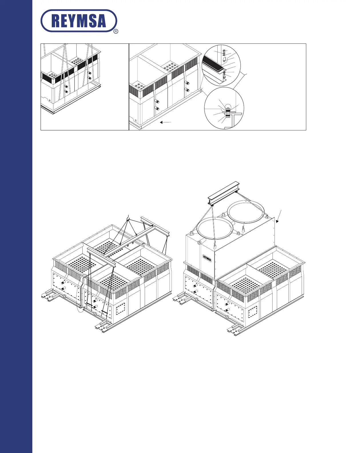
SPREADER FRAME
UPPER SECTION 1
LOWER SECTION
VERTICAL FLANGES
Figure A-23: Lower section installation for quadruple fan
tower
Figure A-24: Upper section 1 quadruple fan tower
J. Place the Upper section 2 on top of Lower section 2, making sure that the bolt holes on Upper section 2
are aligned with the perforations on Lower section 2, then proceeds to bolt together the vertical anges
of sections 1 & 2; use rst the galvanized bolts and nuts to join sections (supplied by REYMSA), once both
sections are well together then replace galvanized bolts with the stainless steel nut and bolts sets supplied
by REYMSA.
Installation