REYMSA COOLING TOWERS, INC.
www.reymsa.com
14
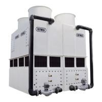
H. Assemble the upper section with the lower section, the upper section comes assembled with u-bolts for
lifting; then using a crane assemble both parts, use a guide pin to align bolt holes as the sections are being
set (See gure A-30). Make sure that the recirculation water inlet, and the recirculation water outlet are
on the same side of the tower when assembled.
Figure A-30: Upper Body Section Installation for HFC-F models
Remove
U-bolts
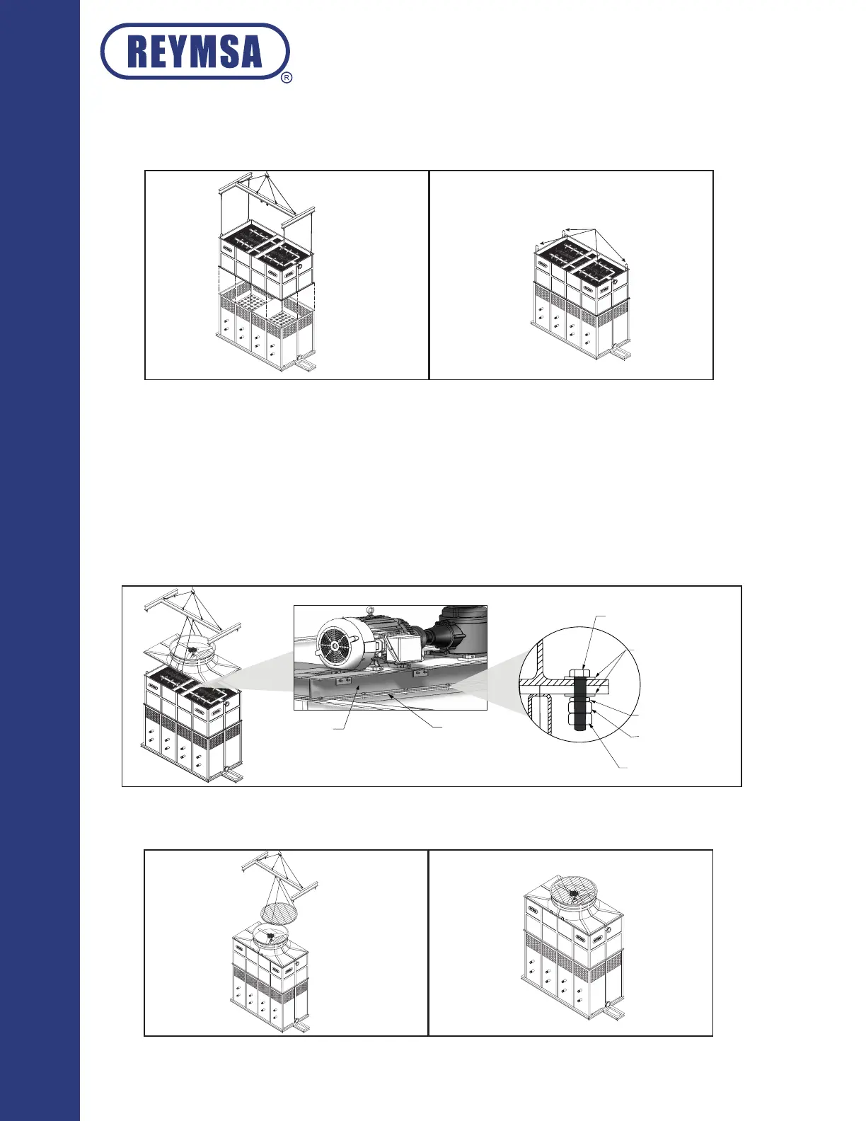
I. HFC-F models have a section called “Fan Deck” which is at the top of the Tower structure. The Fan Deck
with duct contains a gear drive fan and a motor mounted in a structural Hot Dip Galvanized Steel, and a
corrosion resistant safety screen mesh.
J. Before the lifting of the Fan Deck Section, remove the safety screen mesh on the oor.
K. Assemble Fan Deck Section with Body Section, making sure that the holes on the Fan Deck Section are
aligned with the holes on the Body Section. Secure it with stainless steel bolts.
L. After The Fan Deck has been set in place, proceed to bolt down the Hot Dip Galvanized Steel mechanical
support to the Body Section FRP support inside of the Fan Deck Section (see gure A-31).
Installation
M. Place the corrosion resistant safety screen mesh on top of the Fan Deck Section (see gure A-32).
1
/
2 ” Flat washer
1
/
2 ” Lock washer
1
/
2 ” Nut
1
/
2 ” Safety nut
1
/
2 ” x 2
1
/
2 ” bolts
Figure A-31: Fan duct assembly for HFC-F models
Figure A-32: Screen mersh assembly for HFC-F models
Mechanical Support
(Hot Dip Galvanized Steel)
Body Section
FRP Support