REYMSA COOLING TOWERS, INC.
www.reymsa.com
The
All-Fiberglass
Cooling Towers
29
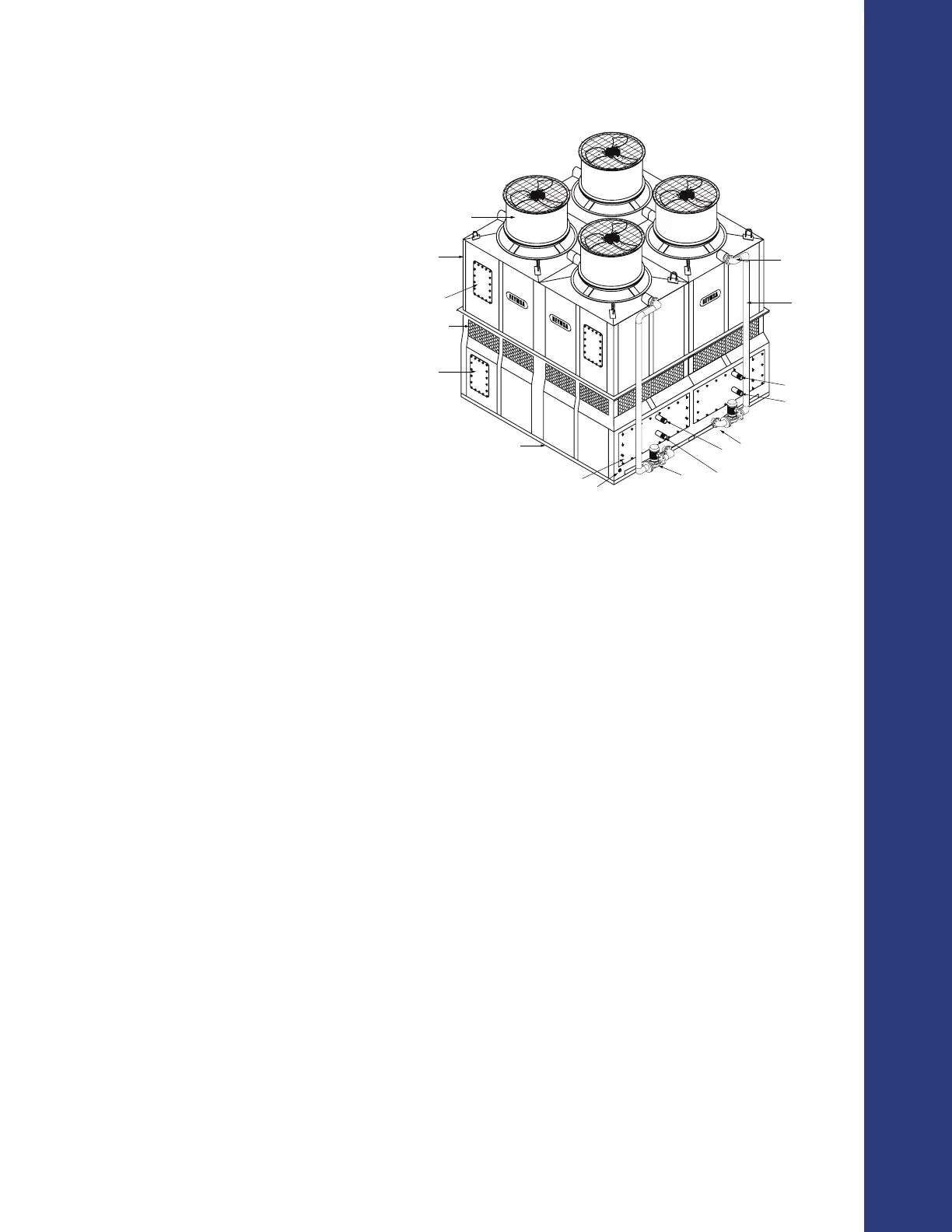
Installation
Figure A-59: Pipe connections for a quadruple fan tower
Principle of operation
▪ Counter-ow - Air movement is vertically upward through the ll, counter to the downward fall of water.
▪ Induced draft - The fan is located on top of the tower, over the ll section so that the air is pulled through
it.
Conguration and tower parts
▪ Suction line (basin section) - The hot water in the basin is suctioned by the spray pump to supply water
to distribution system.
▪ Make-up (basin section) - Make-up water needs to compensate the water losses due to evaporation,
drift and purge. To control make-up water ow, a mechanical oat valve is included by REYMSA as
a standard feature. A NPT connection is provided and marked as Make-up Water. Electric automatic
ll valve with control is available as an optional (refer to section “A.2.8.4. ELECTRIC WATER LEVEL
CONTROL SYSTEM”).
▪ Overow (basin section) - Overow occurs when the water level within a tower basin rises above this
level, the water ows down overow pipe into a sewer. The overow connections are NPT threaded.
▪ Purge (basin section) - Purging is done to remove circulating water high in dissolved solids concentration.
The purge connection is NPT threaded and must have a valve (supplied by others).
▪ Drain (basin section) - The drain is used to remove all the basin water for tower maintenance and
cleaning. The drain connection is NPT and must have a valve (supplied by others).
▪ Process uid (basin/coil section) - The process uid inlet receives to the hot water that needs to be
cooled by the system. The process uid outlet returns the cooled process water. The process uid water
runs inside the coil without having contact with the environment.
▪ Lateral access door (basin section) - Lateral door with access to the cooper coil for maintenance and
revision purposes.
▪ Body/basin section access door - Access for maintenance and revision purposes.
1. FAN SECTION
2. RECIRCULATION WATER INLET
3. AIR INLET LOUVERS
4. UPPER BODY SECTION
5. BASIN SECTION
6. WATER RETURN PIPE
7. RECIRCULATION WATER OUTLET
8. SPRAY PUMP
9. PROCESS FLUID OUTLET
10. PROCESS FLUID INLET
11. STEEL BASE SUPPORT (SUPPLIED BY OTHERS)
12. BODY SECTION ACCESS DOOR (FILL ACCESS)
13. BASIN SECTION ACCESS DOOR (COIL ACCESS)
14. LATERAL ACCESS DOOR (BASIN ACCESS)
15. WATER MAKE-UP
16. OVERFLOW (BACK SIDE)
17. DRAIN (BACK SIDE)
18. PURGE (BACK SIDE)
19. TEMPERATURE SENSOR (BACK SIDE)
20. BASIN HEATER (BACK SIDE)
1
2
3
4
6
7
8
9
10
11
12
13
15
14
9
10