REYMSA COOLING TOWERS, INC.
www.reymsa.com
The
All-Fiberglass
Cooling Towers
7
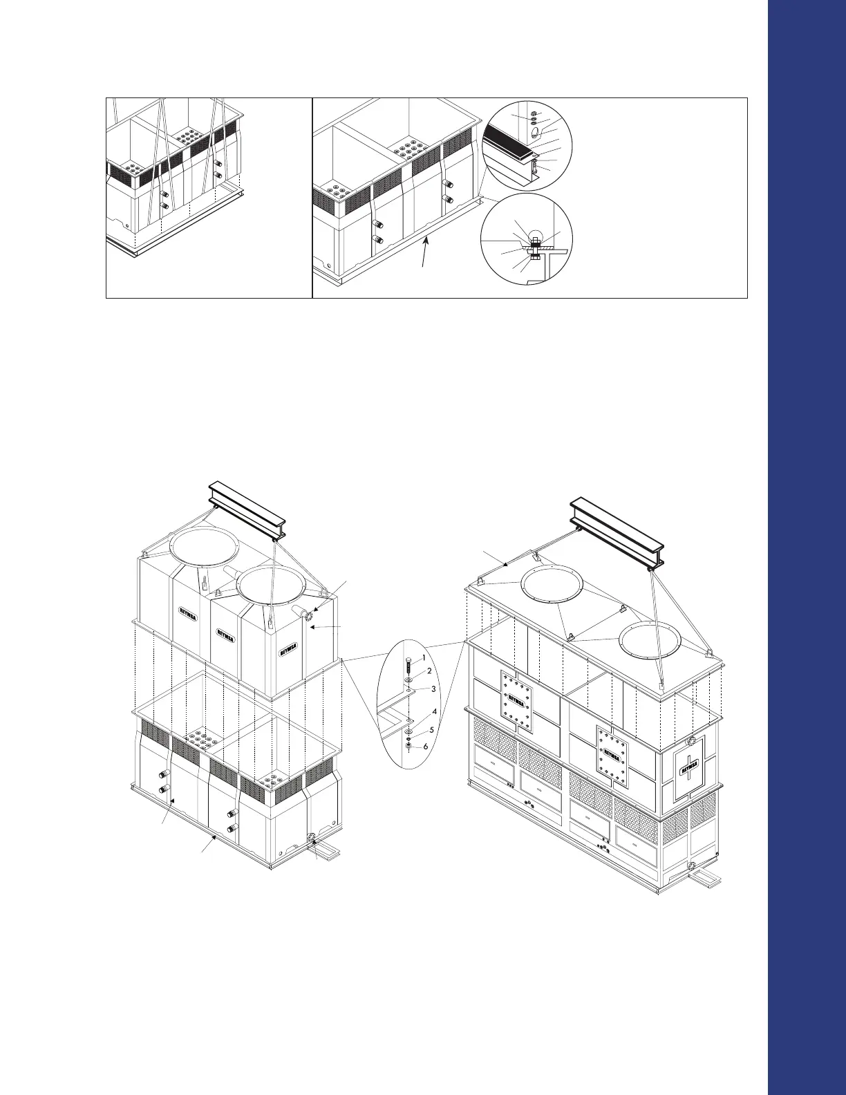
H. Using a crane, assemble the upper section with the lower section, the upper section comes assembled with
u-bolts for lifting; use a guide pin to align bolt holes as the sections are being set. In case that the upper
section comes with detached cover, detailed explanations are described bellow for assembly.
I. Models 819, 822, 827, 1619, 1622 and 1627, come with the upper section cover separated, for
assembly rst you have to bring together the upper section (provided with steel frame supports placed
under the ange and u-bolts for lifting), with the lower section, and then put the upper section cover on the
top, using the u-bolts and a spreader beam to assemble both parts. Bolts are to remain after assemble.
ASSEMBLY HOLES
1. 1/2” X 2.5” BOLT
2. 1/2” FLAT WASHER
3. 5/8” HOLE
4. 1/2” FLAT WASHER
5. 1/2” LOCK WASHER
6. 1/2” NUT
WATER INLET PORT
UPPER BODY COVER
UPPER SECTION
LOWER
SECTION
STEEL BASE SUPPORT
(SUPPLIED BY OTHERS)
WATER OUTLET
Figure A-15: Fan duct, upper and lower parts installation
Installation
Figure A-13: Basin lifting (optional) Figure A-14: Typical anchorage for a double fan tower
1
2
3
4
6
7
8
5
1
2
3
7
8
5
STEEL BASE STRUCTURE
(SUPPLIED BY OTHERS)
4 ANCHORAGE HOLES
(ONE ON EACH CORNER)
1. 3/4” NUT
2. 3/4” LOCK WASHER
3. 3/4” FLAT WASHER
4. 3/4” ANCHORAGE HOLES
5. ISOLATION PAD
6. ≈1” HOLE
7. 3/4” FLAT WASHER
8. 3/4” X 3” BOLT
(SUPPLIED BY OTHERS)