REYMSA COOLING TOWERS, INC.
www.reymsa.com
The
All-Fiberglass
Cooling Towers
1
A. INSTALLATION
A.1. LOCATION
Location of the Closed Circuit Fluid Cooler is important to assure it achieves its desired performance. A bad
location choice could lead into performance, safety and environmental issues. The following considerations
are meant to be a guideline to avoid such problems.
A.1.1. RECIRCULATION AND INTERFERENCE
Recirculation is the recapture of a portion of warm and humid air by the same tower. Interference is caused
when a Closed Circuit Fluid Cooler is situated downwind or in close proximity to a heat-emitting source, like
another Closed Circuit Fluid Cooler, red heaters, are stacks, boilers, etc. and warm air enters the Closed
Circuit Fluid Cooler. Both phenomena causes a variation in the entering air wet bulb temperature, therefore
affecting the Closed Circuit Fluid Cooler performance. To avoid recirculation and interference, consider the
following guidelines:
▪ Remove any obstructions that might prevent the free ow of the entering and exiting air.
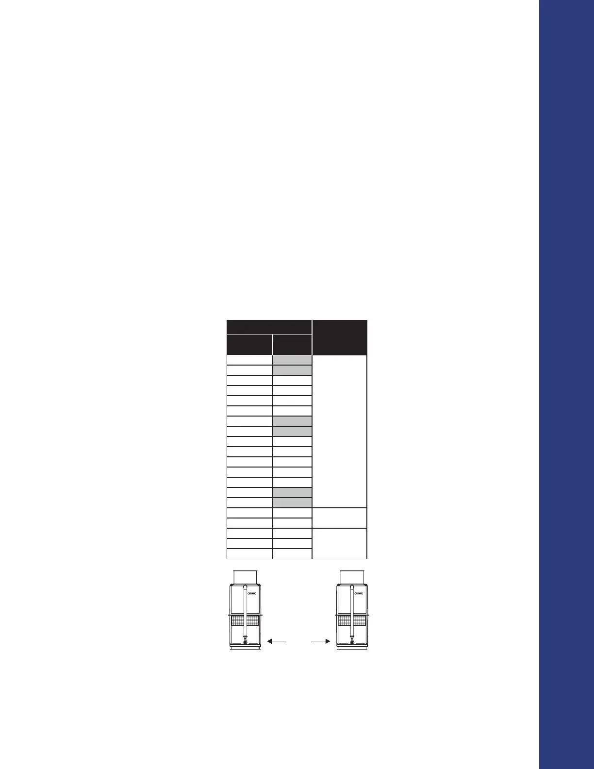
▪ Make sure that the area provides enough clearance for safe operation. Place towers far enough apart
so that discharge air from one tower is not drawn in by another. See Table A-1 and Figure A-1 for
suggested clearances between towers.
For a complete table of minimum distances between towers and obstructions please refer to “APPENDIX C: MINIMUM
DISTANCE BETWEEN TOWERS AND OBSTRUCTIONS”.
Installation
MODEL
MINIMUM
DISTANCE “D”,
FT
HFC HFC-SL
505
6
606
707 707-LS
808 808-LS
810 810-LS
812 812-LS
510
612
714 714-LS
816 816-LS
819 819-LS
822 822-LS
827 827-LS
1010
1212
1414 1414-LS
7
1616 1616-LS
1619 1619-LS
91622 1622-LS
1627 1627-LS
Table A-1: Minimum recommended distance between towers
Figure A-1: Minimum recommended distance between towers
DISTANCE
“D”