REYMSA COOLING TOWERS, INC.
www.reymsa.com
The
All-Fiberglass
Cooling Towers
13
Installation
A.2.4. SINGLE FAN TOWERS (GEAR DRIVEN MODELS)
Follow this procedure to assemble and install single fan Closed Circuit Fluid Cooler with Gear Drive System.
A. Upon the equipment arrives with the end user, check any abnormality or apparent damage in the
packaging before any landing maneuver of the Closed Circuit Fluid Cooler and its components. The
packing list must match the goods received. Any absence or abnormality of the equipment should be
reported immediately and directly to your local REYMSA representative.
B. After verifying the equipment is received in proper conditions, proceed to unload it piece by piece, with
a crane or forklift of the appropriate capacity (see Figure A-28 for reference).
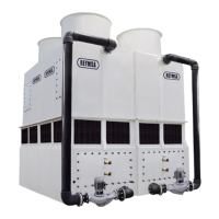
C. For crane lifting, it is recommended to use a minimum elevation angle of 60 ° between the straps and
the horizontal, also pay special attention when lifting the bottom of the tower (basin with copper coil),
because it does not count with lifting brackets due to their weight. Explicit instructions are described below.
D. Surround the lower section of the tower with the straps, placing them through the basin openings (as shown
in Figure A-28), it’s important to use a spreader bar to avoid damage on the upper edge of the tower,
when lifting don’t balance until tensing the straps, pad the strap areas on the tower to avoid scratching.
E. Remove the plastic wrap that surrounds the tower and its components, loosen the nuts and bolts that keep
the basin section attached to the wooden pallet (the body comes unattached), the nuts and bolts are
located at the bottom of the basin (some models comes totally unattached to the pallet).
F. Before tower’s assembly, REYMSA recommends to install a steel base structure that supports the tower’s
operational weight; also place an isolation pad (supplied by others) between the tower and the base
structure for support purposes. Verify that the base structure has the proper dimensions (for construction,
refer to factory certied drawings). For more information, see section “A.3.1. LEVELING AND TOWER
SUPPORTS”.
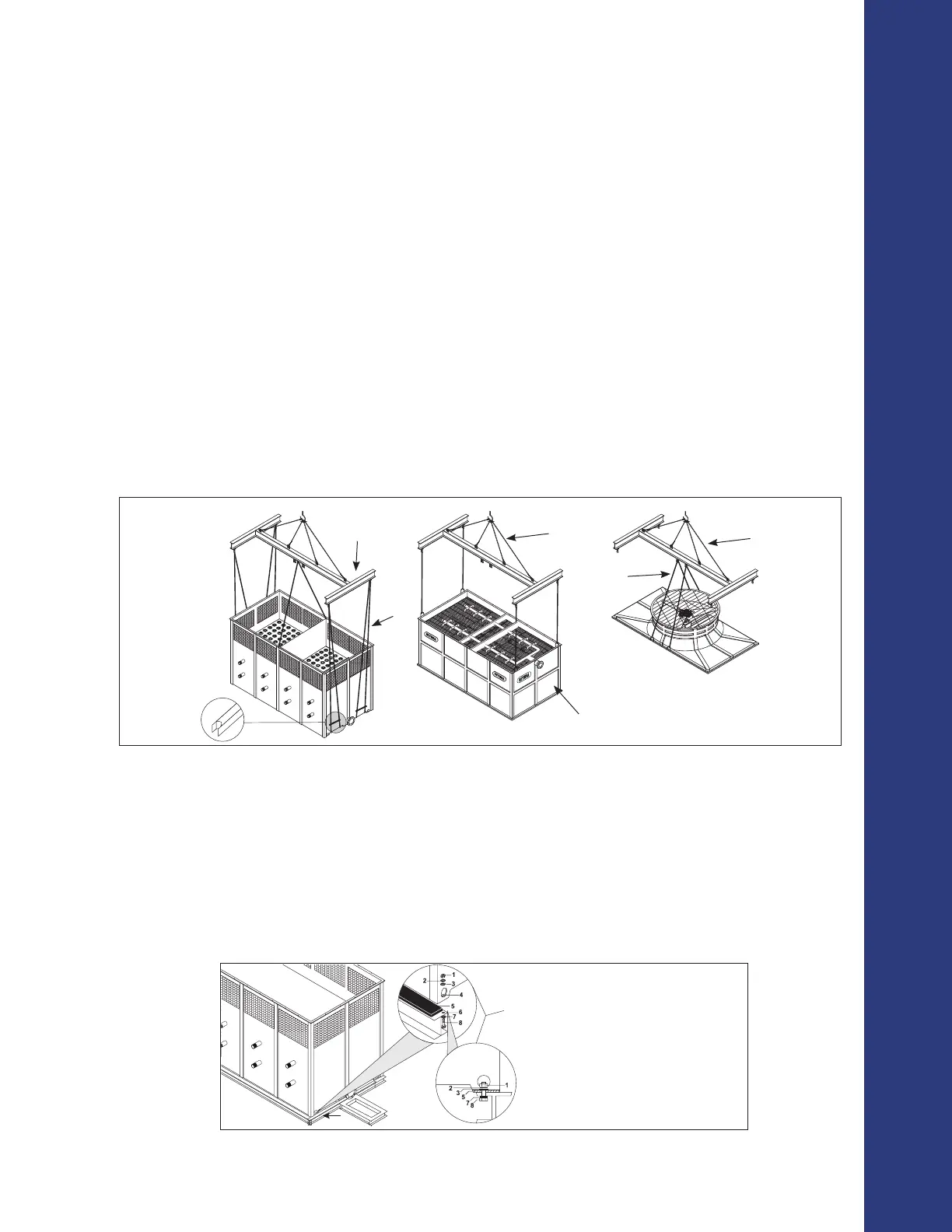
G. Place the lower section of the tower (basin with copper coil) on top of the isolation pad and the steel
base structure, making sure that the anchorage holes on the bottom of the tower are aligned with the
perforations of the base. Then proceed to bolt it down and secure it with stainless steel nut and bolt sets
(supplied by others, see Figure A-29 ).
Figure A- 28: Crane lifting for HFC-F models
Basin
Spreader Bar
Body
Fan Duct
Spreader Bar
Cable
Straps
Rope
Cable
Figure A- 29: Typical anchorage for HFC-F models
4 ANCHORAGE HOLE
(ONE ON EACH CORNER)
1. 3/4” NUT
2. 3/4” LOCK WASHER
3. 3/4” FLAT WASHER
4. 3/4” ANCHORAGE HOLES
5. INSOLATION PAD
6. ≈1” HOLE
7. 3/4” FLAT WASHER
8. 3/4” x 3” BOLT
(SUPPLIED BY OTHERS)