REYMSA COOLING TOWERS, INC.
www.reymsa.com
16
7. Install the spray pump and spray line assembly with the gaskets on the face of the anges aligning
the bolt holes. (Repeat the steps 5 & 6).
8. The joints must be inspected during the start-up to assure that there are no water leaks in the
connections.
Unnecessary over torque will damage the ange
CAUTION
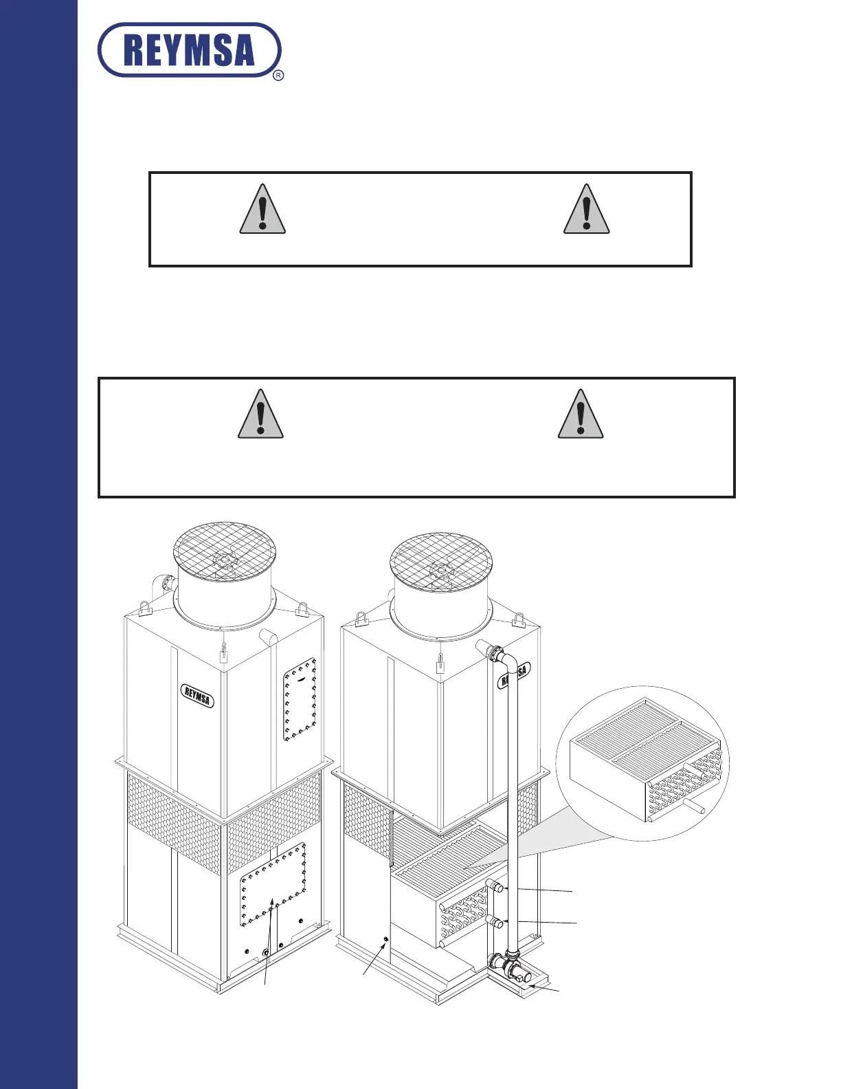
A.2.6. COPPER COIL UNIT
The copper coil unit comes already installed (See gure A-34).
The hot process water connects to the lower port (process uid inlet), and the cold process water connects to
the upper port (process uid outlet). For Maintenance purposes please refer to section “D.8. COPPER COIL
UNIT” of this manual.
COPPER COIL UNIT
PROCESS FLUID OUTLET PORT
PROCESS FLUID INLET PORT
STEEL BASE SUPPORT
(SUPPLIED BY OTHERS)
ACCESS DOOR
CHEMICAL
TREATMENT SUPPLY
Figure A-34: Copper coil unit
Installation
The chemical treatment supply connection is not factory installed. This connection must be installed
on the basin (below the copper coil) to dilute the chemicals in the water. Direct exposure of the
copper coil to the chemicals may accelerate corrosion.
CAUTION