REYMSA COOLING TOWERS, INC.
www.reymsa.com
4
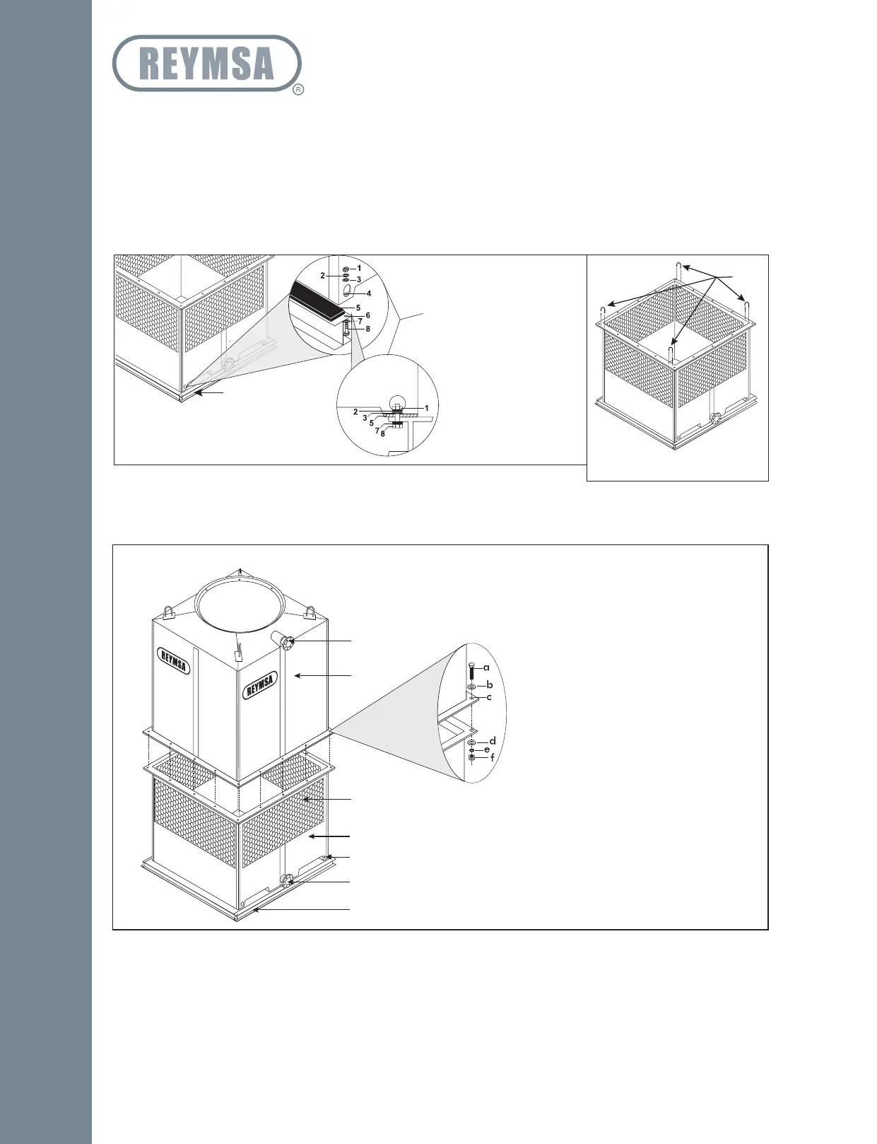
F. Place the basin section on top of the isolation pad and the steel base structure, making sure that the
anchorage holes on the bottom of the Tower are aligned with the perforations of the base. Then proceed
to bolt it down and secure it with stainless steel nut and bolt sets (supplied by others) as shown on Figure
A-5.
G. After the basin has been set in place, remove the U-bolts located on the flange before installing the next
section (see Figure A-6).
4 ANCHORAGE HOLES
(ONE ON EACH CORNER)
1. 3/4” Nut
2. 3/4” Lock Washer
3. 3/4” Flat Washer
4. 3/4” Anchorage Holes
5. Isolation Pad
6. ≈1” Hole
7. 3/4” Flat Washer
8. 3/4” X 3” Bolt
9. (Supplied by others)
Steel base support
(Supplied by others)
Figure A-5: Typical anchorage for a Single Fan Tower
Remove
Figure A-6: Removing U-bolts
from basin for a Single Fan Tower
Figure A-7: Body and basin sections installation on RT-A, RT-B, and RT-C
1. Hot Water Inlet
2. Body Section
3. 4 Anchorage Holes (one on each corner):
a. 1/2” X 2.5” Bolt
b. 1/2” Flat Washer
c. 5/8” Hole
d. 1/2” Flat Washer
e. 1/2” Lock Washer
f. 1/2” Nut
4. Louvers
5. Basin Section
6. Anchorage Holes
7. Cold Water Outlet
8. Steel Base Support (supplied by others).
1
2
3
5
4
7
6
8
RT-A, RT-B & RT-C
Installation