REYMSA COOLING TOWERS, INC.
www.reymsa.com
The
All-Fiberglass
Cooling Towers
47
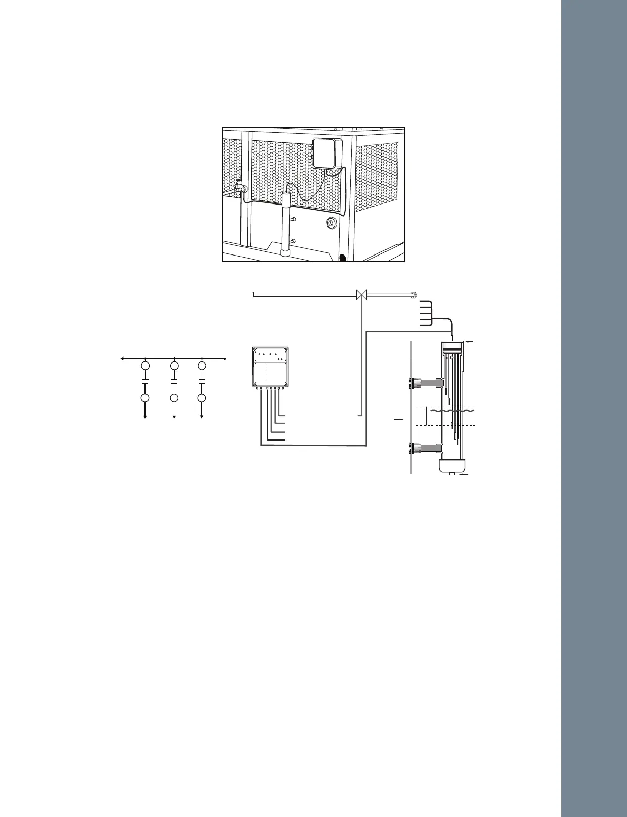
Figure A-113: Electrical Connections & Water Level Control Parts
Sensor Low Voltage Raceway
AC Power Input
Sensor Wire
Water Supply
Internal Relays (N.O.)
are rated 30 amps
at 250VAC.
Low Level Alarm
POWER
ALARM
FILL
LOW
ALARM
TESTING
HIGH
ALARM
PRESS TO TEST
Reference - BLACK
Low Alarm - BROWN
Fill Level ON - WHITE
Fill Level OFF- RED
High Alarm - GREEN
High Level Alarm
SENSOR
CONTROLLER
FILL Level Control: ON - OFF
Operating range
Purge
flange
M.O.L
5/8" Hole (2)
LOW
ALARM
HIGH
ALARM
120 VAC
50-60 Hz
TO LOADS
120 VAC, 30 AMP, MAX.
VALVES
ON-OFF
FILL
LEVEL
Figure A-112: Electric water level control system
Sensor assembly installation
1. Assemble the waterline control in a convenient location where splashing water or dew will not affect the unit. The
unit and the input/output wiring must be securely attached to the mounting surface.
2. The sensor assembly (Figure A-113) must be made so that the end of the PVC pipe is below the minimum level of
water to be maintained.
3. Secure the sensor assembly to the basin of the tower with the two ½" npt fittings.
NOTE: In the PVC pipe there are two small
5
∕
"
vent holes near the top of the housing. Be certain these two vent holes
are not covered or obstructed in any way. They must be clear to allow the sensor assembly to function properly.
4.- The probe assembly is supplied with the sensor cable pre-installed. Be sure to route the cable in an appropriate
place and shorten the length if it is determined if necessary. The cable can be shortened to a more suitable length
as needed.
NOTE: The sensor wires must not be spliced in order to increase the length.
5.- After connecting the cable to a tight PVC compression connector, install it at the bottom of the Waterline WLC
casing. The output control cables are connected to the output terminals of the relays using the user supplied ¼” plug
connector.
NOTE: the rating on the relay should not be exceeded.
6.- Use water tight PVC conduit for all connections and route the location desired by the end user. If the depth of the
probes need to be seen while the sensor assembly is installed mark the sensor probe levels on the outside of the pipe
with a “Sharpie”. The center of the nominal fill level is marked with a black button in the outer pipe.
Installation
A.10.4 ELECTRIC WATER LEVEL CONTROL SYSTEM
Electric water level control system is an optional accessory offered by REYMSA includes water level controller,
stilling chamber, and solenoid valve for water make up (see Figure A-112 & Figure A-113).
8