REYMSA COOLING TOWERS, INC.
www.reymsa.com
The
All-Fiberglass
Cooling Towers
11
A.2.3 QUADRUPLE FAN TOWERS
Follow this procedure to assemble and install Quadruple Fan Cooling Towers.
A. Upon the arrival of the equipment to its final destination, check for any apparent damage to the packaging
before unloading the Cooling Tower. The packing list must match with the received merchandise. Any
equipment absences or abnormality must be reported to your local REYMSA representative.
B. After verifying the equipment is received in proper condition, proceed to unload it piece by piece, with
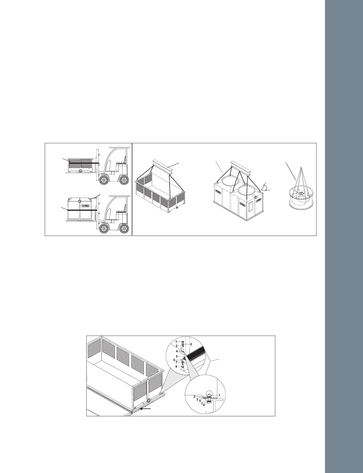
a crane or forklift of the appropriate capacity (see Figure A-23 and Figure A-24 for reference).
C. For crane lifting, it’s recommended to use a minimum lifting angle of 60º between the strap and the
horizontal. The basin section of the Double Fan towers has U-bolts on the flange for lifting, one on each
corner. Place the straps through the u-bolts (as shown in Figure A-24) and use a spreader frame to avoid
damage on the upper edge of the Tower. Don’t balance until tensing the straps.
D. Remove the plastic wrap that surrounds the Tower and its components, loosen the nuts and bolts that keep
the basin section attached to the wooden pallet (the body comes unattached), the nuts and bolts are
located at the bottom of the basin (some models comes totally unattached).
E. Before Tower’s assembly, REYMSA recommends to install a steel base structure that supports the Tower’s
operational weight; also place an isolation pad (supplied by others) between the Tower and the base
structure for support purposes. Verify that the base structure has the proper dimensions (for construction,
refer to factory certified drawings). For more information, see section “A.11.1 LEVELING AND TOWER
SUPPORTS”.
F. Place the basin section of the Tower on top of the isolation pad and the base structure; Secure it with the
stainless steel nut and bolt sets (supplied by others) as shown on Figure A-25.
BASIN SECTION
BODY SECTION
FAN DUCT
Cable
Rope
Spreader bar
Figure A-24: Quadruple Fan Tower crane lifting
60°
BASIN SECTION
BODY SECTION
Fork extensions
6 ft minimum pallet length
Straps
Cable
Figure A-23: Quadruple Fan Tower fork
lifting
Straps
Figure A-25: Typical anchorage for a Quadruple Fan Tower
STEEL BASE STRUCTURE
(SUPPLIED BY OTHERS)
4 ANCHORAGE HOLES
(ONE ON EACH CORNER)
1. 3/4” Nut
2. 3/4” Lock Washer
3. 3/4” Flat Washer
4. 3/4” Anchorage Holes
5. Isolation Pad
6. ≈1” Hole
7. 3/4” Flat Washer
8. 3/4” X 3” Bolt
(Supplied by others)
Installation