REYMSA COOLING TOWERS, INC.
www.reymsa.com
14
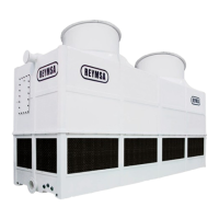
N. Remove fan guard.
O. Then cradle/straddle the fan support with the straps (as shown in Figure A-32)so you can lift the fan duct
with a crane and assemble it.
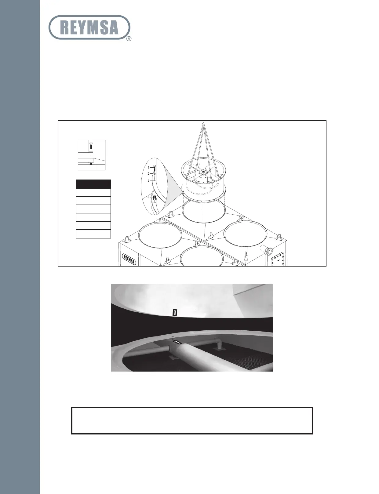
P. Identify each fan duct, they are labeled with a number on the inside of the lower edge. For a correct
installation, this number must match the number on the distribution manifold of the corresponding body
section. Place fan duct 1 on the corresponding receiving flange on top of body section 1 of the Tower;
make sure the bolt holes and the marks inside the fan duct and receiving flange are aligned (Figure A-32
and A-33). Secure it with the stainless steel nut and bolt sets supplied by REYMSA.
Q. Continue to place fan duct 2 on top of body section 1, following the same instructions mentioned on
previous step. Follow the step N, O and P for the remaining fan ducts.
Figure A-33: Fan Duct alignment
Figure A-32: Fan Duct installation for a Quadruple Fan Tower
ASSEMBLY HOLES
1. 1/2” X 2.5” Bolt
2. 1/2” Flat Washer
3. 5/8 Hole
4. 1/2” Screw Insert
(Factory assembled)
RECESSED FLANGE
MODELS
RT-1414
RT-1616
RT-1619
RT-1622
RT-1624
RT-1627
NOTE
If your Tower is for a low sound application and it includes a fan adaptor please see
Section “A.7 LOW SOUND FAN COOLING TOWER: FAN ADAPTORS”.
Installation