REYMSA COOLING TOWERS, INC.
www.reymsa.com
The
All-Fiberglass
Cooling Towers
43
A.10.2 VIBRATION SWITCH
Vibration switches provided by REYMSA are shock sensitive mechanisms for shutdown of the Cooling Tower
fan motors. These switches use a magnetic latch to ensure reliable operation whenever shutdown protection
from damaging shock/vibration is desired. As the level of vibration or shock increases an inertia mass exerts
force against the latch arm and forces it away from the magnetic latch causing the latch arm to operate the
contacts. Sensitivity is obtained by adjusting the amount of the air gap between the magnet and the latch
arm plate.
Note: During severe cold weather conditions, ice can form on the fan blades of Cooling Tower causing
excessive vibration. The vibration switch shuts down the motor avoiding potential damage by shock or
vibration.
Installation instructions
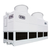
Firmly secure the unit to the equipment using the base foot and mount to a satisfactory location, see Figure
A-104 as an example of a recommended location. The vibration switch is factory mounted (if bought with
the Cooling Tower); wiring to the control panel needs to be done in the planned location of the Cooling
Tower.
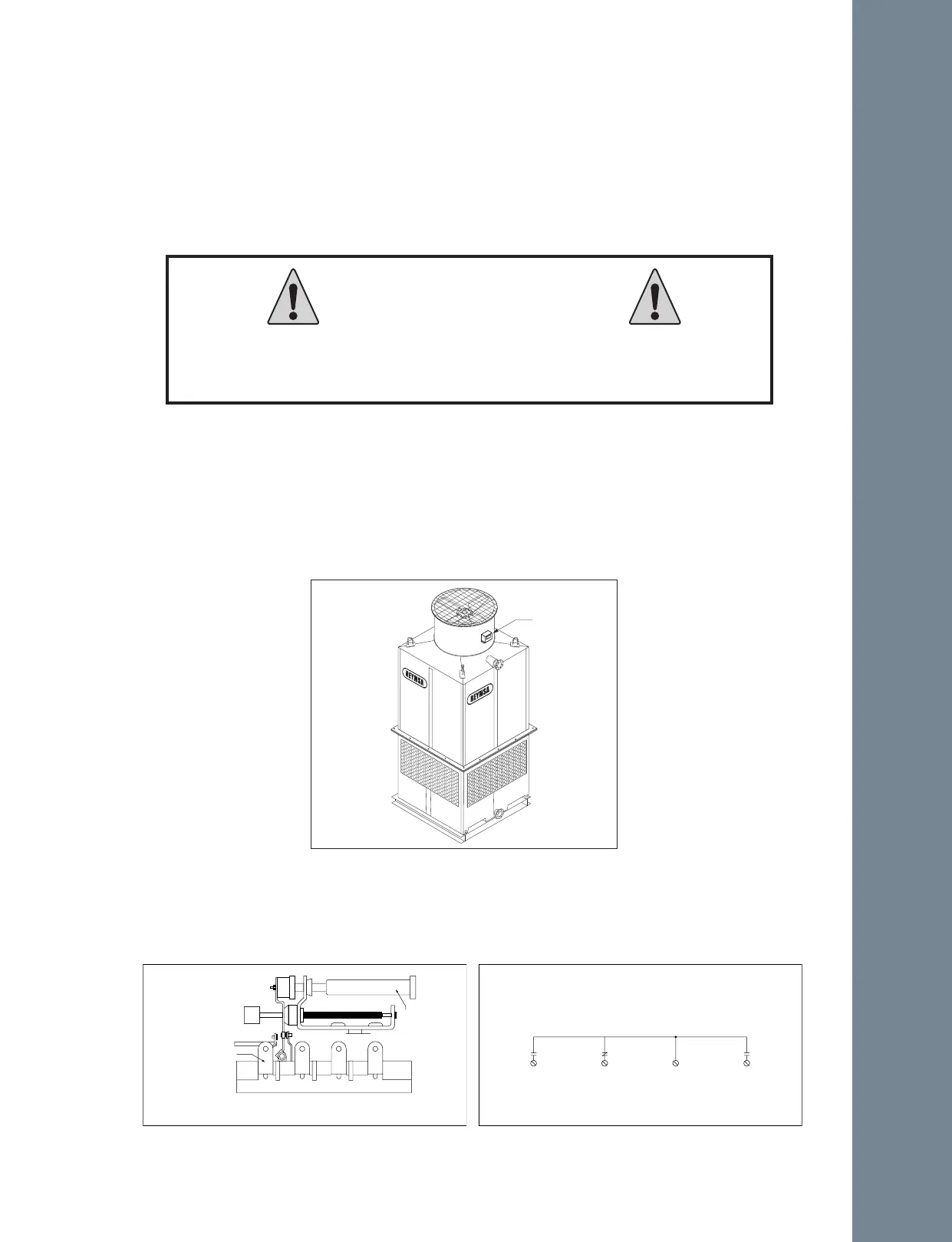
Make the necessary electrical connections to the vibration switch. See Figure A-105 for electrical terminal
locations and Figure A-106 for a typical electrical diagram. See section “C.1.2 CONFIGURATION AND
START-UP FOR ABB ACH550-UH” for vibration switch connections on VFD.
Stop fan motor and disconnect all electrical power, tag and lock in off
position before beginning installation.
Failure to do so may result in personal injury or property damage.
CAUTION
N01NC COM N02
Sensitivity
Adjustment
Spdt Switch
Terminals
Figure A-105: Internal switches
N01
NC COM
N02
Contact Rating
5A @480 VAC
Figure A-106: Vibration Switch Electric Diagram
Vibration
Switch
Figure A-104: Vibration Switch recommended location
Installation