REYMSA COOLING TOWERS, INC.
www.reymsa.com
50
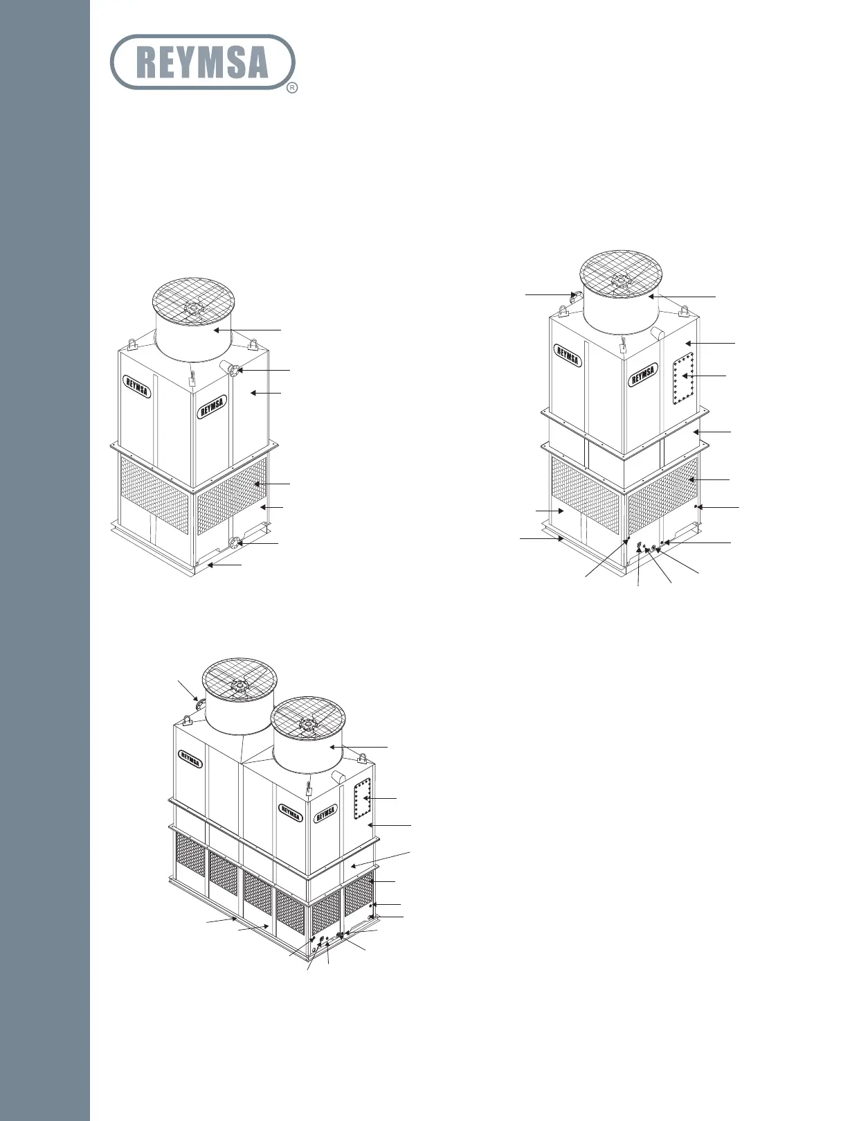
Piping should be adequately sized in accordance with accepted engineering principles. All piping and other
external equipment must be self-supported, totally independent from the Cooling Tower.
Also, in case your area experiences extreme cold weather, care must be taken to protect all piping located
on the exterior of the building from freezing (refer to section “C.4.1 COLD WEATHER OPERATION”). See
Figure A-117, Figure A-118 and Figure A-119 for general scheme of the different connections in REYMSA
Cooling Towers.
1. Fan Section
2. Hot Water Inlet
3. Body Section (Rt-A, Rt-B, Rt-C)
4. Upper Body Section (Rt-D)
5. Access Door
6. Lower Body Section (Rt-D)
7. Louvers
8. Basin Section
9. Water Make-Up
10. Purge
11. Drain
12. Basin Heater
13. Temperature Sensor
14. Overflow
15. Cold Water Outlet
16. Steel Base Support (Supplied By Others)
Figure A-117: Pipe connections for a Single Fan Tower
1
1
2
2
3
4
5
6
7
7
8
8
9
10
11
12
13
14
15
16
16
RT-A, RT-B & RT-C RT-D
Figure A-118 Pipe connections for a Double Fan Tower (RT-D)
1. Fan Section
2. Hot Water Inlet
3. Access Door
4. Body Section (Rt-A, Rt-B, Rt-C Models)
5. Lower Body Section (Only In Rt-D Models)
6. Louvers
7. Basin Section
8. Water Make-Up
9. Anchorage Holes
10. Purge
11. Drain
12. Basin Heater
13. Temperature Sensor
14. Overflow
15. Cold Water Outlet (Back Side)
16. Steel Base Support (Supplied By Others)
1
2
3
4
5
6
7
8
9
10
11
12
13
14
16
RT-D
Installation