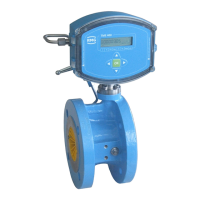
Figure 1: Turbine meter sectional drawing
There is a permanent magnet on the end disc of the turbine shaft which induces a
voltage pulse in the Wiegand sensor with every rotation. This pulse is supplied to the
measuring unit of the meter head, which detects the operating volume flow directly as
a main totalizer and determines the gas volume flowing through the meter by adding
up the pulses and division by the meter factor (number of pulses per m3). This oper-
ating volume is shown in the display of the TME400.
 Loading...