With the RMG turbine meters, these straighteners fulfill the requirements of technical
guideline G 13 and are approved with approval number D 81 / 7.211.10 for turbine
meters.
1.4.2.7.
Standards / guidelines
All RMG turbine meters have passed upstream pertubation measurements according
to OIML recommendation IR-32/89, Annex A, with slight and heavy upstream per-
tubation. Therefore, this meter design fulfills the installation conditions according to
technical guideline G 13, section 1. The PTB testing vol. 29 and 30, testing of volume
gas meters with air at atmospheric pressure and high-pressure testing rules apply as
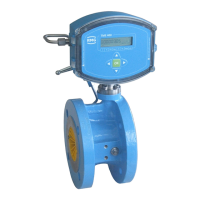
a testing requirement. The RMG turbine meter TME400 conforms to EN12261. The
measuring accuracy in the range of 0.2 Q
max
to Q
max
is between 1.0 % to 1.5 %
(see chapter 1.4.2.9 Measuring accuracy). The TME400 has an electronic suppres-
sion by external shut-down of the totalizer of the slow down cutoff of the turbine
wheel after the flow is stopped.
 Loading...