The LF output transmits this HF frequency with a variable scaling factor (chapter
4.3.3.1 Volume / Meters).
1.4.2.
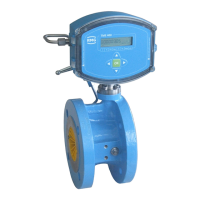
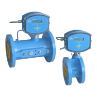
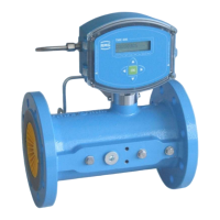
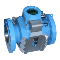
Integrating the turbine meter into the pipeline
Turbine meters from RMG are equipped with connecting flanges. For a secure con-
nection, the connection dimensions of the flanges of the pipelines to be connected
must match the connection dimensions of the flanges of the device.
• ANSI pressure levels: flange connection dimensions correspond to the
standard ASME B 16.5.
• DIN pressure levels: flange connection dimensions correspond to the
standard DIN EN 1092.
1.4.2.1.
Seals
•
Flat seals: k0 x KD = 20 x bD | k1 = 1.3 x bD [N/mm]
•
Grooved seals: k0 x KD = 15 x bD | k1 = 1.1 x bD [N/mm]
•
Spiral seals: k0 x KD = 50 x bD | k1 = 1.4 x bD [N/mm]
•
Octagonal ring-joint seal: KD = 480 N/mm2
Refer to the tables below for the recommended dimensions.
Flat seals (DIN 2690 / EN 12560-1 Form IBC)
 Loading...