Rockwell Automation Publication 1769-UM021I-EN-P - May 2018 191
Use I/O Modules with CompactLogix 5370 L2 Controllers Chapter 8
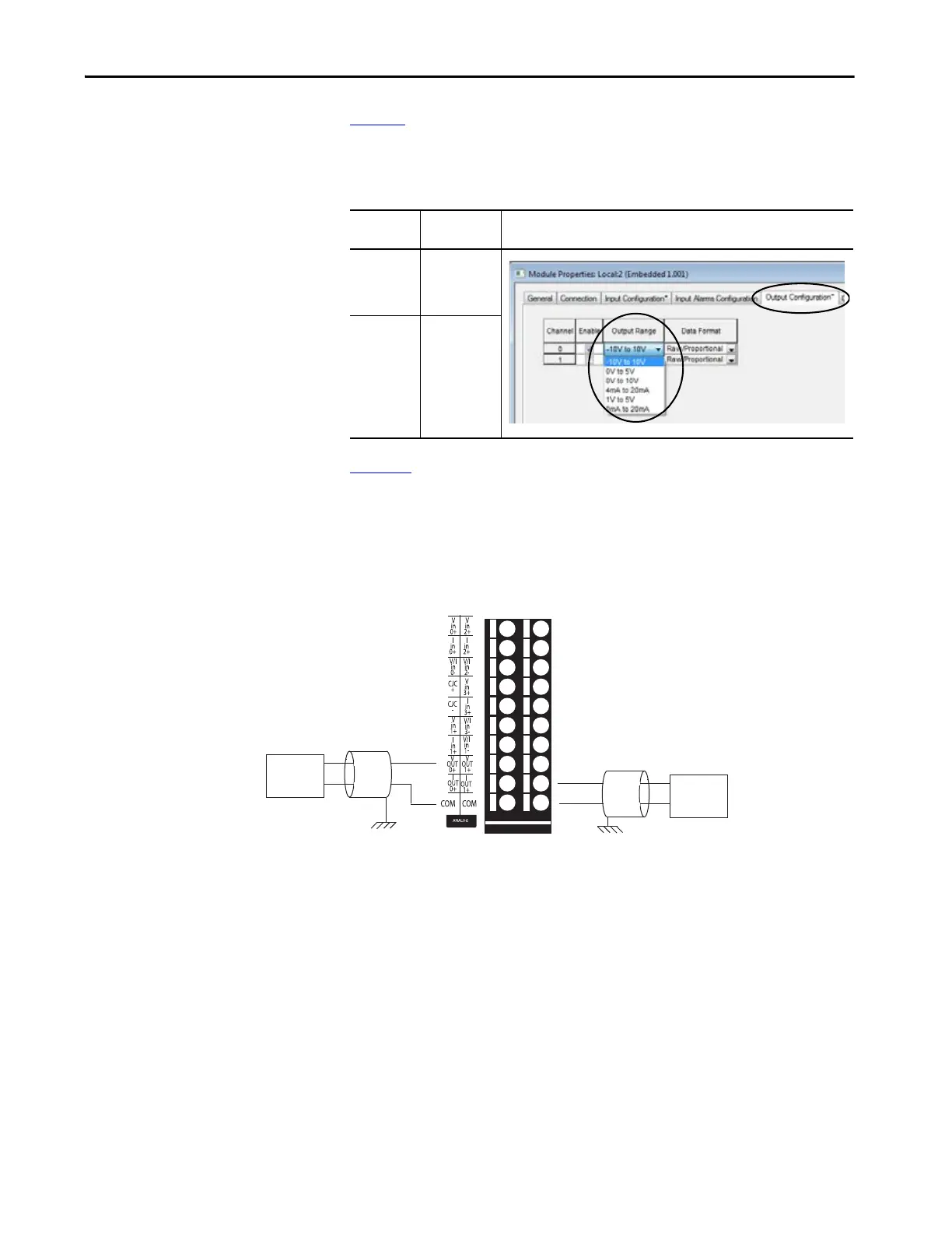
Tab le 12 lists the available embedded analog output channel types and ranges
for the channel type. The configuration choices are made on the Output
Configuration tab of the Module Properties dialog box, as shown in the table.
Figure 33
shows an example of wiring input devices to the analog output points
on the 1769-L27ERM-QBFC1B controller when it is operating in voltage or
current mode.
Figure 33 - 1769-L27ERM-QBFC1B Controller Analog Output Wiring Diagrams
Table 12 - Output Types
Output
Type
Output
Ranges
Project Configuration
Voltage • -10…10V
• 0…5V
• 0…10V
• 1…5V
Current • 4…20 mA
• 0…20 mA
Voltage
Load
Earth Ground
Current
Load
Voltage Analog
Output Wiring
Diagram
Current Analog
Output Wiring
Diagram
Earth Ground
 Loading...


