Rockwell Automation Publication 856T-UM001B-EN-P - April 2021 11
Chapter 1 Product Overview
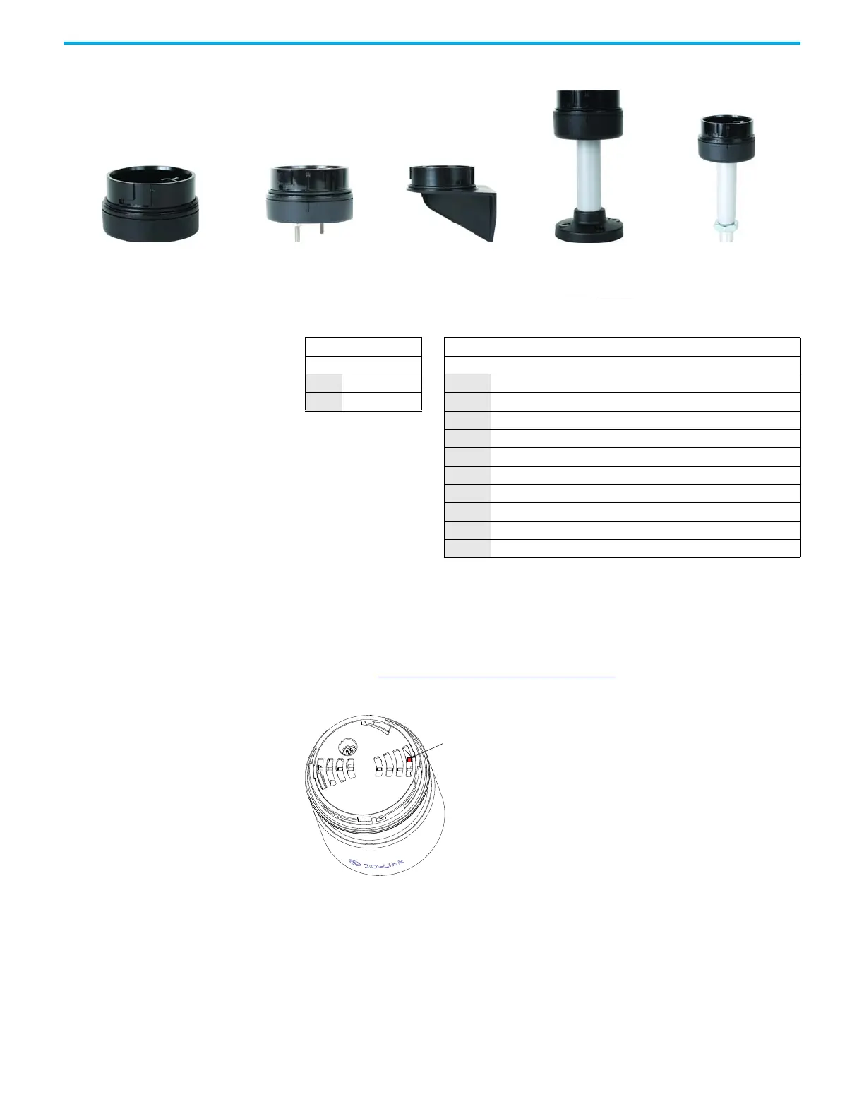
Figure 2 - Base Mounting Adapters
When power is applied to the device, the module runs a self-test routine to
verify the health of its internal electronic components and the result of this test
is visible via a bicolor status indicator that is mounted inside the module but
visible from the top. In addition, this status indicator also displays if the device
is communicating with the IO-Link Master. For more information on these
results, see Power On Self Test (POST)
on page 43.
Figure 3 - Status Indicator Location on IO-Link Module
Pole mountVertical mountSurface with screwsSurface 1/2 in. NPT Threaded tube mount
856T – BMA P10
ab
ab
Housing Color Mounting Style
Code Description Code Description
BMA Black SN NPT surface mount, Type 4/4X/13
VM Vertical mount
SH Surface mount NPT, Type 4/4X/13, preinstalled mounting hardware
P10 10 cm (3.9 in.) aluminum pole mount
P25 25 cm (9.8 in.) aluminum pole mount
P40 40 cm (15.7 in.) aluminum pole mount
P60 60 cm (23.6 in.) aluminum pole mount
T10 10 cm (3.9 in.) threaded tube (M20)
T25 25 cm (9.8 in.) threaded tube (M20)

 Loading...


