12 Rockwell Automation Publication 856T-UM001B-EN-P - April 2021
Chapter 1 Product Overview
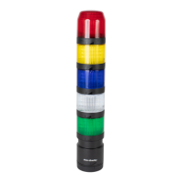
Wiring The 856T-B24LC module has an embedded 5-pin M12 connector at the bottom
of the unit. This connector accepts standard cordsets when connecting the
device with a Class B Master. Figure 4
shows the pin arrangement.
Figure 4 - M12 Connector Location and Pin Arrangement
Figure 5 - Connection Example: 856T-B24LC Module to the 1734-4IOL Master
IMPORTANT See Class A IO-Link Master Connection Consideration on page 45 for
specific considerations when connecting the 856T-B24LC module to an
Allen-Bradley Class A IO-Link master.
Table 1 - Wiring the 856T-B24LC Module to the 1734-4IOL Master
856T-B24LC Module
889D Cordset
Wire Color
1734-4IOL
Connection
M12 Connector Pin # Signal
1 L+ Brown Voltage
2P24White—
3 L- Blue Common
4 C/Q Black Channel
5N24Gray—
5
2
1
4
3
Pin Signal Description
1 L+ Power supply (+)
2 P24 P24 (port Class B)
3 L- Power supply (-)
4 C/Q SIO/SDCI
5 N24 N24 (port Class B)
Class B
M12-5
1734-4IOL
Point I/O Adapter
NC
0
NC
1
Chas
Gnd
2
Chas
Gnd
3
C
4
C
5
V
7
V
6
Ch 0
0
Ch 1
1
Ch 2
2
Ch 3
3
C
4
C
5
V
7
V
6
Black
Blue
Brown
N24 Gray
P24 White
Device
Power
Supply
-
+
IMPORTANT Use an 889D-F5AC-* cordset to connect the 856T-B24LC module
to the 1734 IO-Link master.

 Loading...


