Rockwell Automation Publication 1756-UM542A-EN-P - September 2014 7
Chapter 1
Installation
Hardware
The 1756HP-TIME module operates within the ControlLogix platform. All
power required for the operation of the module is supplied by the ControlLogix
backplane.
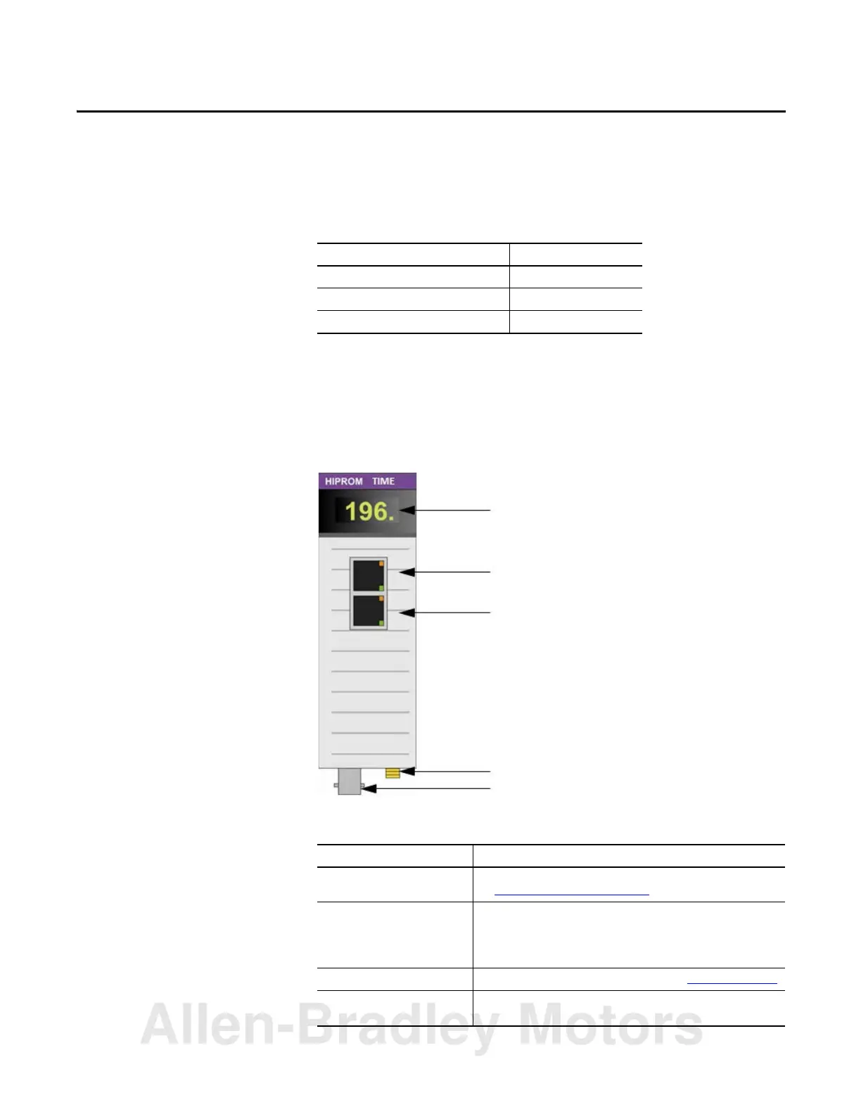
Figure 1 - 1756HP-TIME Module, Front View
Table 1 - 1756HP-TIME Module Hardware Descriptions
Topic Page
Hardware 7
GPS Antenna 8
Software 8
Hardware Description
Status indicators and messages Provides status and operational information for the 1756HP-TIME module.
See 1756HP-TIME Module Status on page 35.
Ethernet connector 1 and
Ethernet connector 2
(uses Rockwell Automation®
dual-port switch technology)
PTP and NTP time synchronization uses the Ethernet connections.
Note: This connection is not a bridge to the backplane and cannot be used to
view m
odules on the backplane.
GPS SMA connector Connect the GPS bullet antenna to this connector. See GPS Antenna on page 8.
IRIG-B coaxial connector Connect the IRIG-B network cable to this connector. The 1756HP-TIME module
can be configured as a master clock or a slave clock on the IRIG-B network.
Status Indicators and Messages
Ethernet Connection 1
Ethernet Connection 2
GPS Subminiture Version A (SMA) Connector
IRIG-B Coaxial Connector
Allen-Bradley Motors
 Loading...


