20 Rockwell Automation Publication 2080-UM002L-EN-E - November 2021
Chapter 1 Hardware Overview
Micro850 and Micro870 controllers support Ethernet crossover cables
(2711P-CBL-EX04).
Ethernet Status Indication
Micro850 and Micro870 controllers also support two LEDs for EtherNet/IP™ to
indicate the following:
• M
odule status
•N
etwork status
See Troubleshooting
on page 263 for descriptions of Module and Network
status indicators.
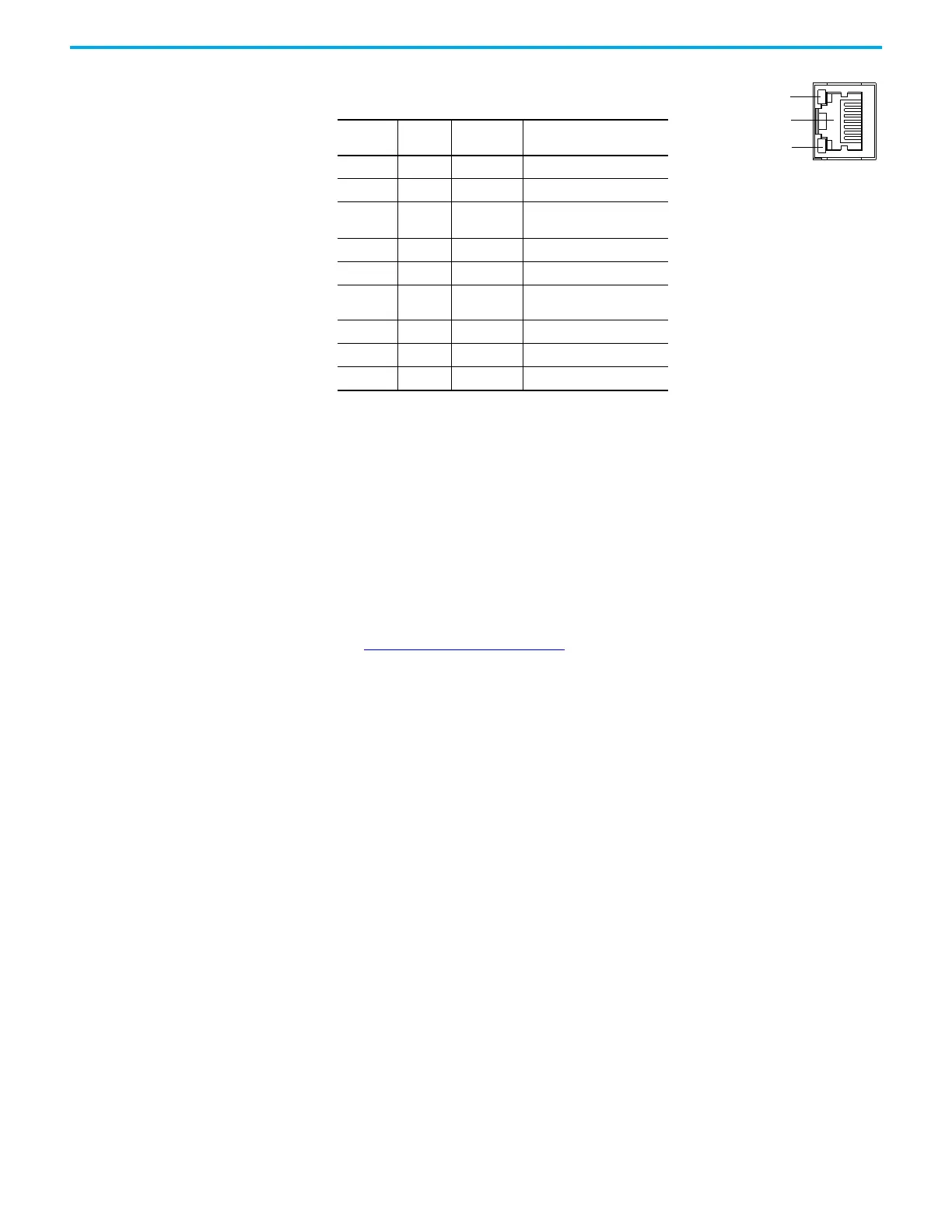
yellow LED
green LED
RJ-45 connector
RJ-45 Ethernet Port Pin Mapping
Contact
Number
Signal Direction Primary Function
1 TX+ OUT Transmit data +
2 TX- OUT Transmit data -
3RX+IN
Differential Ethernet Receive
Data +
4 Terminated
5 Terminated
6RX-IN
Differential Ethernet Receive
Data -
7 Terminated
8 Terminated
Shield Chassis Ground
The yellow status LED indicates Link
(solid yellow) or No Link (off).
The green status LED indicates
activity (blinking green) or no activity
(off).

 Loading...


