206 Rockwell Automation Publication 2080-UM002L-EN-E - November 2021
Appendix A Specifications
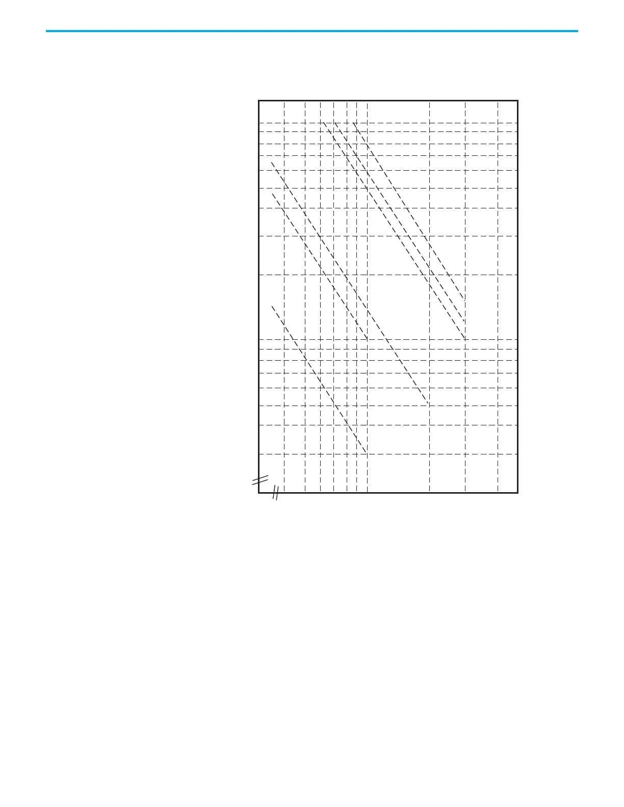
Relay Chart for Micro830,
Micro850, and Micro870
Controllers
PTO Output Duty Cycle Error
Turn On/Off time for the Micro830, Micro850, and Micro870 controllers for
the PTO output port is 0.2 μs and 2.5 μs max, respectively. Duty cycle error is:
Positive error = 2.5 μs * F
Negative error = -0.2 μs * F
The plot below shows duty cycle error vs. frequency.
To get the duty cycle error at a certain frequency, for example, the user sets
frequency to 20 kHz, and sets duty cycle to 30% in Connected Components
Workbench software, then actual duty cycle is
AC 250 V cos φ = 0.4
AC 125 V cos φ = 0.4
AC 125 V
resistive load
AC 250 V
resistive load
DC 30 V
resistive load
DC 30 V T = 7 ms
0.5 1.0 2.0 3.0
5
3
10
20
30
50
100
Switching capacity (A)
Number of operations (X10)
Relay life

 Loading...


